What is Servo Motor?

his is nothing but a simple electrical motor, controlled with the help of servomechanism. If the motor as controlled device, associated with servomechanism is DC motor, then it is commonly known DC Servo Motor. If the controlled motor is operated by AC, it is called AC Servo Motor.

Servo Motor Theory


There are some special types of application of electrical motor where rotation of the motor is required for just a certain angle not continuously for long period of time. For these applications, some special
types of motor are required with some special arrangement which makes the motor to rotate a certain angle for a given electrical input (signal). For this purpose servo motor comes into picture. This is normally a simple DC motor which is controlled for specific angular rotation with the help of additional servomechanism (a typical closed loop feedback control system). Now day’s servo system has huge industrial applications.

Servo motor applications are also commonly seen in remote controlled toy cars for controlling the direction of motion and it is also very commonly used as the motor which moves the tray of a CD or DVD player. Besides these, there are other hundreds of servo motor applications we see in our daily life. The main reason behind using a servo is that it provides angular precision, i.e. it will only rotate as much we want and then stop and wait for next signal to take further action. This is unlike a normal electrical motor which starts rotating as and when power is applied to it and the rotation continues until we switch off the power. We cannot control the rotational progress of electrical motor, but we can only control the speed of rotation and can turn it ON and OFF.

Now we come to the specific answer of the question “what is servo motor?”
Servo motor is a special type of motor which is automatically operated up to certain limit for a given command with help of error-sensing feedback to correct the performance.
Servo Motor System

What is Capacitor and Capacitance? Types of Capacitors

We are now all very much familiar with the fact that static charges can be generated very easily, if we can somehow apply sufficient frictional force between two bodies under consideration. For example, pulling a transparent tape off a roll results in the separation of small amounts of positive and negative charge, which can be accumulated separately within the two bodies. This particular phenomena gave rise to the concept of capacitors, which is simply a device for charge storage.

capacitor
The earliest written account of charging by friction dates back as far as the 6th Century BC, when a Greek scientist named Thales of Miletus noted that, a piece of amber rubbed with animal fur acquired the ability to pick up small bits of material. This is the result of charged particles For the next 2 million years, wherever the subjects of electricity were studied, two different materials had to be taken and rub together to create a separated island of positive and negative charges.

Now coming straight to Eighteenth Century Europe, where electricity was one of the major hot topics in the field of Research and development, and many inventions were done with electrostatic machines that generated charge by friction. While friction is an easy and inexpensive mean to separate charge for use in electric experiments, the amount of charge available was quite small. If electricity was going to be anything other than an irritating side effect of walking on the carpet, some means for increasing the amount of charge available for experiments had to be found.
The first device for storing charge or a capacitor was discovered in the winter of 1745-46 by two electricians working independently:
Firstly Dr. Ewald Georg von Kleist a scientist from Poland built a device, consisted of a medicine bottle; partly filled with water and sealed with a cork. A nail was then pushed through the cork into the water. Now holding the bottle in one hand, the nail was brought in contact with the terminal of an electrostatic machine which allowed it to acquire charge for some time. Then, when Dr. Von Kleist touched the nail to remove it from the stopper while still holding the bottle, the separated charges were able to reunite by flowing through his body, and he received a bitter shock, which later went on to become one of the biggest boons for mankind.

Simultaneously; another scientist from Holland, Sir Pieter Van Musschenbroek built his own device, and the experiences with it were almost the same as Von Kleist’s, but with three major exceptions.
Firstly, a visiting student Andreas Cunaeus to Pieter van’s laboratory made the shocking discovery,not van Musschenbroek himself. Secondly, he made many significant improvements to the device; one of them being, removal of water and then wrapping the jar with metallic foil, inside out. And thirdly, he wrote to his colleagues to tell them all about his new discovery. It was from this point, that the world came to know about capacitors, and later on several papers were published and scientists all over the globe studied about the capacitance of an electrical circuit at large, to develop a modern day capacitor, that we encounter these days.
So, to store more energy in a capacitor, the voltage across the element must be increased. This essentially means that more electrons will be added to the negative plate, which is at the expense of electrons being taken away from the positive plate, thus necessitating a flow of current from the positive to negative direction.
Conversely, the reverse is also true, as to release energy from a capacitor; the voltage across it must be reduced sufficiently. This means some of the excess electrons on the negative plate must be returned to the positive plate, thus reducing the value of current flowing through the element.

What is Capacitor?

Capacitor is a passive element that stores electric charge statistically and temporarily as an static electric field. It is composed of two parallel conducting plates separated by non-conducting region that is called dielectric, such as vacuum, ceramic, air, aluminum, etc.
The capacitance formula of the capacitor is represented by,

C is the capacitance that is proportional to the area of the two conducting plates (A) and proportional with the permittivity ε of the dielectric medium. The capacitance decreases with the distance between plates (d). We get the greatest capacitance with a large area of plates separated by a small distance and located in a high permittivity material. The standard unit of capacitance is Farad, most commonly it can be found in micro-farads, pico-farads and nano-farads.

General uses of Capacitors

  1. Smoothing, especially in power supply applications which required converting the signal from AC to DC.
  2. Storing Energy.
  3. Signal decoupling and coupling as a capacitor coupling that blocks DC current and allow AC current to pass in circuits.
  4. Tuning, as in radio systems by connecting them to LC oscillator and for tuning to the desired frequency.
  5. Timing, due to the fixed charging and discharging time of capacitors.
  6. For electrical power factor correction and many more applications.

Charging a Capacitor

Capacitors are mainly categorized on the basis of dielectric used in them. During choosing a specific type of capacitors for a specific application, there are numbers of factors that get considered. The value of capacitance is one of the vital factors to be considered. Not only this, many other factors like, operating voltage, allowable tolerance stability, leakage resistance, size and prices are also very important factors to be considered during choosing specific type of capacitors.

We know that capacitance of a capacitor is given by,

Hence, it is cleared that, by varying ε, A or d we can easily change the value of C. If we require higher value of capacitance (C) we have to increase the cross-sectional area of dielectric or we have to reduce the distance of separation or we have to use dielectric material with stronger permittivity.

If we go only for the increasing area of cross-section, the rise of the capacitor may become quite large; which may not be practically acceptable. Again if we reduce only the distance of separation, the thickness of dielectric becomes very thin. But the dielectric cannot be made too thin in case its dielectric strength in exceeded.

Types of Capacitors

The various types of capacitors have been developed to overcome these problems in a number of ways.

Paper Capacitor

It is one of the simple forms of capacitors. Here, a waxed paper is sandwiched between two aluminium foils.
Process of making this capacitor is quite simple. Take place of aluminium foil. Cover this foil with a waxed paper. Now, cover this waxed paper with another aluminium foil. Then roll up this whole thing as a cylinder. Put two metal caps at both ends of roll. This whole assembly is then encapsulated in a case. By rolling up, we make quite a large cross-sectional area of capacitor assembled in a reasonably smaller space.
paper capacitor

Air Capacitor

There are two sets of parallel plates. One set of plates is fixed and another set of plates is movable. When the knob connected with the capacitor is rotated, the movable set of plates rotates and overlapping area as between fixed and movable plates vary. This causes variation in effective cross-sectional areas of the capacitor. Consequently, the capacitance varies when one rotates the knob attached to the air capacitor. This type of capacitor is generally used to tune the bandwidth of a radio receiver.
variable air capacitor

Plastic Capacitor

When various plastic materials are used as dielectric material, the capacitors are said to be plastic capacitors. The plastic material may be of polyester, polystyrene, polycarbonate or poly propylene. Each of these materials has slightly different electrical characteristics, which can be used to advantage, depending upon the proposed application.

This type of capacitors is constructional, more or less same as paper capacitor. That means, a thin sheet one of the earlier mentioned plastic dielectrics, is kept between two aluminium foils. That means, here the flexible thin plastic sheet is used as dielectric instead of waxed paper. Here, the plastic sheet covered by aluminium foil from two sides, is first rolled up, then fitted with metal end caps, and then the whole assembly is encapsulated in a case.

Plastic Film Capacitor

Plastic capacitor can be made also in form of film capacitor. Here, thin strips or films of plastic are kept inside metallic strips. Each metallic strip is connected to side metallic contact layer alternatively; as shown in the figure below. That means, if one metallic strip is connected to left side contact layer, then the very next is connected to right side contact layer. And there are plastic films in between these metallic strips. The terminals of this type of capacitors are also connected to side contact layer and whole assembly is covered with insulated non metallic cover as shown.
plastic capacitor

Silvered Mica Capacitor

A silvered mica capacitor is very accurate and reliable capacitor. This type of capacitors has very low tolerance. But on the other hand, cost of this capacitor is quite higher compared to other available capacitors in the market. But this high cost capacitor can easily be compensated by its high quality and performance. A small ceramic disc or cylinder is coated by silver compound. Here, electrical terminal is affixed on the silver coating and the whole assembly is encapsulated in a casing.

Ceramic Capacitor

Construction of ceramic capacitor is quite simple. Here, one thin ceramic disc is placed between two metal discs and terminals are soldered to the metal discs. Whole assembly is coated with insulated protection coating as shown in the figure below.
Ceramic Capacitor

Mixed Dielectric Capacitor

The way of constructing this capacitor is same as paper capacitor. Here, instead of moving waxed paper as dielectric, paper impregnated with polyester is used as dielectric between two conductive aluminium foils.

Electrolyte Capacitor

Very large value of capacitance can be achieved by this type of capacitor. But working voltage level of this electrolyte capacitor is low and it also suffers from high leakage current. The main disadvantage of this capacitor is that, due to the use of electrolyte, the capacitor is polarized. The polarities are marked against the terminals with + and – sign and the capacitor must be connected to the circuit in proper polarity.

A few micro meter thick aluminium oxide or tantalum oxide film is used as dielectric of electrolyte capacitor. As this dielectric is so thin, the capacitance of this type of capacitor is very high. This is because; the capacitance is inversely proportional to thickness of the dielectric. Thin dielectric obviously increases the capacitance value but at the same time, it reduces working voltage of the device. Tantalum type capacitors are usually much smaller in size than the aluminium type capacitors of same capacitance value. That is why, for very high value of capacitance, aluminium type electrolyte capacitors do not get used generally. In that case, tantalum type electrolyte capacitors get used.

Aluminium electrolyte capacitor is formed by a paper impregnated with an electrolyte and two sheets of aluminium. These two sheets of aluminium are separated by the paper impregnated with electrolyte. The whole assembly is then rolled up in a cylindrical form, just like a simple paper capacitor. This roll is then placed inside a hermetically sealed aluminium canister. The oxide layer is formed by passing a charging current through the device, and it is the polarity of this charging process that determines the resulting terminal polarity that must be subsequently observed. If the opposite polarity is applied to the capacitor, the oxide layer is destroyed.

Material Dielectric constant Dielectric Strength Volts/.001 inch
Air 1 80
Paper(Oiled) 3-4 1500
Mica 4-8 1800
Glass 4-8 200
Porcelain 5 750
Titanates 100-200 100

CAUTION: NEVER DISCHARGE A CAPACITOR WHILE IT IS CONNECTED TO THE CIRCUIT VOLTAGE, WHETHER THE VOLTAGE SOURCE IS A BATTERY OR AC POWER.


Video presentation of construction of different types of capacitors


Electrical Bus System and Electrical Substation Layout

There are many different electrical bus system schemes available but selection of a particular scheme depends upon the system voltage, position of substation in electrical power system, flexibility needed in system and cost to be expensed.

The Main Criteria’s To be Considered During Selection of one Particular Bus – Bar Arrangement Scheme Among Others

  1. Simplicity of system.
  2. Easy maintenance of different equipments.
  3. Minimizing the outage during maintenance.
  4. Future provision of extension with growth of demand.
  5. Optimizing the selection of bus bar arrangement scheme so that it gives maximum return from the system.

Some very commonly used bus bar arrangement are discussed below-

SSingle Bus System

Single Bus System is simplest and cheapest one. In this scheme all the feeders and transformer bay are connected to only one single bus as show.

Advantages of Single Bus System

  1. This is very simple in design.
  2. This is very cost effective scheme.
  3. This is very convenient to operate.

Disadvantages of Single Bus System

single bus system

  1. One but major difficulty of these type of arrangement is that, maintenance of equipment of any bay cannot be possible without interrupting the feeder or >transformer connected to that bay.
  2. The indoor 11 KV switchboards have quite often single bus bar arrangement.

Single Bus System with Bus Sectionalizer

Some advantages are realized if a single bus bar is sectionalized with circuit breaker. If there are more than one incoming and the incoming sources and outgoing feeders are evenly distributed on the sections as shown in the figure, interruption of system can be reduced to a good extent.

Advantages of Single Bus System with Bus Sectionalizer

If any of the sources is out of system, still all loads can be fed by switching on the sectional circuit breaker or bus coupler breaker. If one section of the bus bar system is under maintenance, part load of the substation can be fed by energizing the other section of bus bar.
single section bus system

Disadvantages of Single Bus System with Bus Sectionalizer

  1. As in the case of single bus system, maintenance of equipment of any bay cannot be possible without interrupting the feeder or transformer connected to that bay.
  2. The use of isolator for bus sectionalizing does not fulfill the purpose. The isolators have to be operated ‘off circuit’ and which is not possible without total interruption of bus – bar. So investment for bus-coupler breaker is required.

Double Bus System

  1. In double bus bar system two identical bus bars are used in such a way that any outgoing or incoming feeder can be taken from any of the bus.
  2. Actually every feeder is connected to both of the buses in parallel through individual isolator as shown in the figure.double bus system

By closing any of the isolators one can put the feeder to associated bus. Both of the buses are energized and total feeders are divided into two groups, one group is fed from one bus and other from other bus. But any feeder at any time can be transferred from one bus to other. There is one bus coupler breaker which should be kept close during bus transfer operation. For transfer operation, one should first close the bus coupler circuit breaker then close the isolator associated with the bus to where the feeder would be transferred and then open the isolator associated with the bus from where feeder is transferred. Lastly after this transfer operation he or she should open the bus coupler breaker.

Advantages of Double Bus System

Double Bus Bar Arrangement increases the flexibility of system.

Disadvantages of Double Bus System

The arrangement does not permit breaker maintenance with out interruption.

Double Breaker Bus System

In double breaker bus bar system two identical bus bars are used in such a way that any outgoing or incoming feeder can be taken from any of the bus similar to double bus bar system. Only difference is that here every feeder is connected to both of the buses in parallel through individual breaker instead only isolator as shown in the figure. By closing any of the breakers and its associated isolators one can put the feeder to respective bus. Both of the buses are energized and total feeders are divided into two groups, one group is fed from one bus and other from other bus similar to previous case. But any feeder at any time can be transferred from one bus to other. There is no need of bus coupler as because the operation is done by breakers instead of isolator. For transfer operation, one should first close the isolators and then the breaker associated with the bus to where the feeder would be transferred and then he or she opens the breaker and then isolators associated with the bus from where feeder is transferred.
double breaker bus system

One and A Half Breaker Bus System

This is an improvement on the double breaker scheme to effect saving in the number of circuit breakers. For every two circuits only one spare breaker is provided. The protection is however complicated since it must associate the central breaker with the feeder whose own breaker is taken out for maintenance. For the reasons given under double breaker scheme and because of the prohibitory costs of equipment even this scheme is not much popular. As shown in the figure that it is a simple design, two feeders are fed from two different buses through their associated breakers and these two feeders are coupled by a third breaker which is called tie breaker. Normally all the three breakers are closed and power is fed to both the circuits from two buses which are operated in parallel. The tie breaker acts as coupler for the two feeder circuits.
During failure of any feeder breaker, the power is fed through the breaker of the second feeder and tie breaker, therefore each feeder breaker has to be rated to feed both the feeders, coupled by tie breaker.
one and half breaker bus system

Advantages of One and A Half Breaker Bus System

During any fault on any one of the buses, that faulty bus will be cleared instantly without interrupting any feeders in the system since all feeders will continue to feed from other healthy bus.

Disadvantages of One and A Half Breaker Bus System

This scheme is much expensive due to investment for third breaker.

Main and Transfer Bus System

main and transfer bus system
This is an alternative of double bus system. The main conception of Main and Transfer Bus System is, here every feeder line is directly connected through an isolator to a second bus called transfer bus. The said isolator in between transfer bus and feeder line is generally called bypass isolator. The main bus is as usual connected to each feeder through a bay consists of circuit breaker and associated isolators at both side of the breaker. There is one bus coupler bay which couples transfer bus and main bus through a circuit breaker and associated isolators at both sides of the breaker. If necessary the transfer bus can be energized by main bus power by closing the transfer bus coupler isolators and then breaker. Then the power in transfer bus can directly be fed to the feeder line by closing the bypass isolator. If the main circuit breaker associated with feeder is switched off or isolated from system, the feeder can still be fed in this way by transferring it to transfer bus.

Switching Operation for Transferring a Feeder to Transfer Bus from Main Bus without Interruption of Power

  1. First close the isolators at both side of the bus coupler breaker.
  2. Then close the bypass isolator of the feeder which is to be transferred to transfer bus.
  3. Now energized the transfer bus by closing the bus coupler circuit breaker from remote.
  4. After bus coupler breaker is closed, now the power from main bus flows to the feeder line through its main
  5. breaker as well as bus coupler breaker via transfer bus.
  6. Now if main breaker of the feeder is switched off, total power flow will instantaneously shift to the bus coupler breaker and hence this breaker will serve the purpose of protection for the feeder.
  7. At last the operating personnel open the isolators at both sides of the main circuit breaker to make it isolated from rest of the live system.

So, it can be concluded that in Main & Transfer Bus System the maintenance of circuit breaker is possible without any interruption of power. Because of this advantage the scheme is very popular for 33KV and 13 KV system.

Double Bus System with Bypass Isolators

double bus with bypass isolator system
This is combination of the double bus system and main and transfer bus system. In Double Bus System with Bypass Isolators either bus can act as main bus and second bus as transfer bus. It permits breaker maintenance without interruption of power which is not possible in double bus system but it provides all the advantages of double bus system. It however requires one additional isolator (bypass isolator) for each feeder circuit and introduces slight complication in system layout. Still this scheme is best for optimum economy of system and it is best optimum choice for 220 KV system.

Ring Bus System

The schematic diagram of the system is given in the figure. It provides a double feed to each feeder circuit, opening one breaker under maintenance or otherwise does not affect supply to any feeder. But this system has two major disadvantages. One as it is closed circuit system it is next to impossible to extend in future and hence it is unsuitable for developing system. Secondly, during maintenance or any other reason if any one of the circuit breaker in ring loop is switch of reliability of system becomes very poor as because closed loop becomes opened. Since, at that moment for any tripping of any breaker in the open loop causes interruption in all the feeders between tripped breaker and open end of the loop.
ring bus system

« Previous

Next »

Closely Related Articles

Electrical Power Substation Engineering and Layout

Mobile Substation | Portable Substation | Mobile Transformer

Load Curve | Load Duration Curve | Daily Load Curve

More Related Articles

Electrical Power Cable

Types of Overhead Conductor

Testing of Electrical Power Cable | Type Test | Acceptance Test | Routine Test

Conductor Resistance Test of Electrical Power Cables

Test for Thickness of Insulation of Power Cable

Annealing Test for Wires and Conductors

Tensile Test of Conductors

Persulphate Test of Conductor

Wrapping Test for Conductors

Capacitor Bank | Reactive Power Compensation

Types of Capacitor Bank

Specifications or Rating of Power Capacitor Bank

Shunt Capacitor

Switchable Capacitor Bank or Switched Capacitor Bank

Location of Shunt Capacitors

Electrical Insulator | Insulating Material | Porcelain Glass Polymer Insulator

Types of Electrical Insulator | Overhead Insulator

Insulation Coordination in Power System

Electrical Insulator Testing | Cause of Insulator failure

Electrical Transmission Tower Types and Design

Methods of Transmission Tower Erection

Basic Concept of Transmission Tower Foundation

Design of Foundations of Transmission Towers in different Soils

Corona Effect in Power System

Ferranti Effect in Power System

Advantages of Three Phase System over Single Phase System

Inductance in Single Conductor Power Transmission Line

Inductance in Three Phase Transmission Line

Why Supply Frequency 50 or 60 Hz not Other Values than these?

Power System Stability

Load Flow or Power Flow Analysis

Transient Stability in Power System

Flexible AC Transmission Systems (FACTS)

Tariff of electricity in India

Power Factor | Calculation and Power Factor Improvement

Skin Effect in Transmission Lines

Inductance of Two Wire Single Phase Transmission Line

Electrical Power Transmission System and Network

Transmission Line in Power System

Voltage in Power Electric Lines

Short Transmission Line

Medium Transmission Line

Long Transmission Line

Performance of Transmission Line

ABCD Parameters of Transmission Line

Sag in Overhead Conductor

New Articles

MOSFET as a Switch

Relationship of Line and Phase Voltages and Currents in a Star Connected System

555 Timer and 555 Timer Working

Bistable Multivibrator

Monostable Multivibrator

Astable Multivibrator

Please provide your valuable comments
Name : –

Email : – 

Location : –

Your content : –

captcha


electrical4u apps

Electrical Power Cable

​Cables are mainly designed as per requirement. Power cables are mainly used for power transmission and distribution purpose. It is an assembly of one or more individually insulated electrical conductors, usually held together with an overall sheath. The assembly is used for transmission and distribution of electrical power. Electrical power cables may be installed as permanent wiring within buildings, buried in the ground and run overhead or exposed. Flexible power cables are used for portable devices, mobile tools and machinery. These are designed and manufactured as per voltage, current to be carried, operating maximum temperature and purpose of applications desired by customer.

For mining, we give extra mechanical strength to cable with double armouring. For wind power plant customers generally require flexible and UV protected cable with mechanical tough sheath so we design as per their requirement.

Rating of Power Cable


Short Circuit Rating


It happens frequently that the conductor size necessary for an installation is dictated by its ability to carry short-circuit current rather than sustained current. During a short –circuit, there is a sudden inrush of current for a few cycles followed by a steadier flow of current for a short period until the protection switchgear operators, normally between 0.1-0.3 seconds

Conductor Size and Material Insulation Material Operating Maximum Temperature Short Circuit Rating
120 sq-mm Copper conductor PVC Insulation 70° C 13.80 KA/SEC
120 sq-mm Aluminium conductor PVC Insulation 70° C 9.12 KA/SEC
120 sq-mm Copper conductor PVC Insulation 85° C 12.48 KA/SEC
120 sq-mm Aluminium conductor PVC Insulation 85° C 8.28 KA/SEC

Current Carrying Capacity


Current carrying capacity is an important aspect is the selection of the optimum size of conductor. Voltage drop and short rating is also very important aspect to select the economical and optimum size of conductor.

Continous Current Rating of (Cables laid singly) 2 Core × 16 mm2 2 Core × 25 mm2
(i) In Ground (Ground Temp 30°C) 103 A 131 A
(ii) In Duct (Ground Temp 30°C) 86 A 111 A
(iii) In Air (Ambient AirTemp 40°C) 94 A 125 A


Voltage Drop


The allowable maximum voltage drops from source to load is another aspect of power cable conductor design.
As per
Ohm’s law, V = IR. The first is the choice of material used for the wire. Copper is a better conductor than aluminium and will have less voltage drop than aluminium for a given length and wire size. Wire size is another important factor in determining voltage drop. Larger wire sizes (those with a greater diameter) will have less voltage drop than smaller wire sizes of the same length. In American wire gauge, every 6 gauge decrease gives a doubling of the wire diameter, and every 3 gauge decrease doubles the wire cross sectional area. In the Metric Gauge scale, the gauge is 10 times the diameter in millimetres, so a 50 gauge metric wire would be 5 mm in diameter.

Construction of Power Cable


There are various parts of a cable to be taken care of during construction. The power cable mainly consists of

  1. Conductor
  2. Insulation
  3. LAY for Multicore cables only
  4. Bedding
  5. Beading/Armouring (if required)
  6. Outer Sheath


electrical power cable

Conductor

Conductors are the only power carrying path in a power cable. Conductors are of different materials. Mainly in cable industry we use copper (ATC, ABC) and aluminium conductors for power cables. There are different types of conductor as Class 1: solid, Class 2 stranded, Class 5 flexible, Class 6 Extra flexible (Mostly used for cords and welding) etc. Conductor sizes are identified with conductor resistance.

Insulation


The insulation provided on each conductor of a cable by mainly PVC (Poly Vinyl Cloride), XLPE (Crosslinked Polyethyelene), RUBBER (Various Types of Rubber). Insulating material is based on operating temperature.

Insulation Material Maximum Operating Temperature
PVC TYPE A 75°C
PVC TYPE B 85°C
PVC TYPE C 85°C
XLPE 90°C
RUBBER – EPR IE-1 90°C
RUBBER – EPR IE-2, EPR IE-3, EPR IE-4, SILICON IE-5 150°C


Cores are identified by colour coding by using different colours on insulation or by number printing on cores

Beading (Inner Sheath)


This portion of the cable is also known as inner sheath. Mostly it is used in Multi core cables. It works as binder for insulated conductors together in multi-core power cables and provides bedding to armour/braid. This portion of the cable is mainly made of PVC( PVC ST-1, PVC ST-2 ), RUBBER (CSP SE-3, CSP SE-4 and PCP SE-3, PCP SE-4, HOFR SE-3 HOFR SE-4, HD HOFR SE-3 ETC)

Armouring


There are mainly G.I. WIRE ARMOURING, G.I. STEEL STRIP armouring. It is done by placing G.I. WIREs, GI or STEEL STRIPs one by one on inner sheath. Armouring is a process which is done mainly for providing earthing shield to the current carrying conductors as well as it is also used for earthing purpose of the cable for safety. When there is any insulation failure in the conductor, the fault current gets enough paths to flow through the armour if it is properly earthed. Providing extra mechanical protection and strength to cable an important added advantage of armouring. In MINING CABLES it is done for conductance

Beading


ANNEALED TINNED COPPER WIRE, NYLON BRAID, COTTON BRAID are mainly used for this purpose. Braiding is the process which gives high mechanical protection to cable and also used for earthing purpose. Significance of braiding is it is more flexible in comparison to armouring.

Outer Sheath


This is outermost cover of the cable normally made of PVC (Poly Vinyl Cloride), RUBBER (Various Types of Rubber) and often the same material as the bedding. It is provided over the armour for overall mechanical, weather, chemical and electrical protection. Outer sheath is protection offered to cable not much electrically but more mechanically.

Material Advantages Disadvantages Max Operating Temperature
PVC Cheap, Durable, Widely available Highest dielectric losses, Melts at high temperatures, Contains halogens 70°C for general purpose 85° C for heat resisting purpose
PE Lowest dielectric losses, High initial dielectric strength Highly sensitive to water treeing, Material breaks down at high temperatures
XLPE Low dielectric losses, Improved material properties at high temperatures Does not melt but thermal expansion occurs, Medium sensitivity to water treeing (although some XLPE polymers are water-tree resistant) 90° C
EPR Increased flexibility, Reduced thermal expansion (relative to XLPE), Low sensitivity to water treeing Medium-High dielectric losses, Requires inorganic filler / additive 90° C
Paper / Oil Low-Medium dielectric losses, Not harmed by DC testing, Known history of reliability High weight, High cost,
Requires hydraulic pressure / pumps for insulating fluid, Difficult to repair, Degrades with moisture
70° C


Mainly above 6 sq mm cables are called power cables but it depends upon the use of cable. For PVC power cables we use IS:1554 and for XLPE power cables we use IS:7098 and for Rubber based power cables we use IS:9968 and other relevant specifications. Power cables are defined by voltage grade and nominal cross sectional area.

What is Standalone Solar Electric System?

​The system which utilizes only solar electric energy as main source of energy is referred as standalone solar electrical system. There are many locations on this earth where no source of electricity is available. At these locations standalone solar electrical system can be the ideal source of electricity. The main advantage of this system is that it does not depend on grid or any other source of electricity. As it does not have any connection with grid or other electric supply line, it is also known as off-grid photovoltaic system. As the sun is the only source of energy in this system it should have some means to make it active even in nighttimes. A storage battery system does the job. Therefore, a storage battery system is an essential component of standalone solar system. But, often this battery system can be omitted from the system if the system is dedicated for the load which to be operated in day times only.

Popular examples of standalone solar system are solar lanterns, solar home lighting systems, solar water pumping systems, etc.

Types of Standalone Solar Systems


Depending upon the use and design there are different types of standalone solar systems.

  1. Standalone Solar (PV) system with only DC load
  2. Standalone Solar (PV) system with DC load and Electronics control circuitry
  3. Standalone Solar (PV) system with DC load, Electronics control circuitry and Battery
  4. Standalone Solar (PV) system with AC/DC load, Electronics control circuitry and Battery.


Standalone Solar (PV) System with only DC Load


This system is simplest among all the standalone solar system.
Standalone Solar (PV) System with only DC Load requires only two main components one the solar module array where the electricity is generated and one or more DC loads where the electricity is consumed. This system serves only during sunny day times. The configuration of this system is quite simple as we told earlier here the solar module array is directly connected to the load no other arrangement is required in between. It is quite natural that the rate of production of electricity in this system varies throughout the day depending upon the intensity and incidence angle of the sunlight. This makes the applications of Standalone Solar (PV) System with only DC Load limited to some specific electrical appliances where the precise operation is not essential. This standalone solar system can be successfully utilized for pumping drinking and irrigation water as in these both cases fixed amount of water is not required to lift every hour.
standalone solar energy system
DC fan can be operated by this system when speed of the fan is not required to be constant throughout the day. In this system the speed of the fan is maximum when the intensity of sunlight is maximum. Hence, maximum pleasant air flow is achieved during maximum hot period of the daytimes. 


Standalone Solar (PV) System with DC Load and Electronic Control Circuit


Standalone Solar (PV) System with only DC Load can be improved by adding an electronic control circuit. This added electronic control circuit to the system, improves the utilization of power generated by the solar module array. This electronic control circuit is normally an electronic solar charge controller (SCC) (voltage or current regulator) or a maximum power point tracker (MPPT). The main purpose of these circuits is to provide regulated
current and voltage to the load. The MPPT circuit is used to extract maximum power from the solar modules under all conditions. Thus, it ensures the best utilization of solar PV modules.
standalone solar energy system with control circuit

Standalone Solar (PV) System with DC Load, Electronic Control Circuit and Battery


A standalone system can be more practical and usable if it is able to serve even in absence of sunlight that is in night times. This can be simply done by adding a storage battery in the system which stores electricity produced during day times. This stored electricity can be utilized when there is no sunlight and in night times. After adding a suitable rated battery, the system becomes a
Standalone Solar (PV) System with DC Load, Electronic Control Circuit and Battery. It is needless to say that this standalone system has four basic components

  • Solar Module Array
  • Electronics Control Circuit
  • Storage Battery System and
  • DC Load


Standalone Solar (PV) System with DC Load, Electronic Control Circuit and Battery
Here solar module charges the battery during daytimes and the battery supplies the load both during day and night. The electronic control circuit plays a vital role here it actually controls the flow of charges into the battery and out of the battery depending upon the system conditions and demands. The control circuit also protects the battery from overcharging as well as over-discharging. This system is most commonly used in solar street light system in remote villages.
LED based solar lanterns which nowadays widely available in the local market are popular examples of Standalone Solar (PV) System with DC Load, Electronic Control Circuit and Battery.

Standalone Solar (PV) System with AC/DC Load, Electronic Control Circuit and Battery


So far we have discussed about the standalone solar energy systems which can only be used for operating DC load but maximum numbers of equipments we use in our daily life are AC operated so some means is required to attach with the
solar energy system so that we can run AC equipment as well with standalone solar system. Inverter is a device which converts DC to AC of specified voltage and frequency. Inverter is basically a DC to AC converter whose input is DC and output is AC of desired voltage and frequency. So if we connect an inverter across the DC output terminals of electronic control device along with the DC load then the system becomes able to run AC equipments as well. As this system can operate both DC and AC load, the system becomes most popular version of standalone solar energy system. Nearly all kinds of DC and AC load can be operated by this system such as AC/DC fan, computer, TV, tube lights, CFL, LED lamps etc. This system is most suitable as alternative of grid electric supply where limited grid electric supply is available.
standalone solar system with inverter
It is needless to say that this standalone system has six basic components

  • Solar Module Array
  • Electronics Control Circuit
  • Storage Battery System and
  • DC Load
  • Inverter
  • AC Load

Wind Turbine.                   Working Types and History of Wind Turbine

How wind turbine works? We all are aware of wind energy that is converted into electrical energy by a wind turbine. But it is very interesting how wind turbine converts kinetic energy from the wind into electrical energy and what are the major parts of a wind turbine.

Major Parts of Wind Turbine


Tower of Wind Turbine


Tower is very crucial part of wind turbine that supports all the other parts. It is not only support the parts but raise the wind turbine so that its blades safely clear the ground and so it can reach the stronger winds at higher elevations. The height of tower depends upon the power capacity of wind turbines. Larger turbines usually mounted on tower ranging from 40 meter to 100 meter.

Nacelle of Wind Turbine


Nacelle is big box that sits on the tower and house all the components in a wind turbine. It houses Power Converter, Shaft, Gearbox, Generator, Turbine controller, Cables, Yaw drive.

Rotor Blades of Wind turbine


Blades are the mechanical part of wind turbine that converts wind kinetic energy into mechanical energy. When the wind forces the blades to move, it transfers some of its energy to the shaft. Blades are shaped like airplane wings blades can be as long as 150 feet.
wind turbin

Shaft of Wind Turbine


The shaft is connected to the rotor. When the rotor spins, the shaft spins as well. In this way, the rotor transfers its mechanical, rotational energy to shaft which enters to an electrical generator on the other end.

Gearbox


The rotor turns the shaft at low speed ex. 20 rpm but for generator to generate electricity we need higher speed. Gearbox increases the speed to much higher value required by most generator to produce electricity.
For example, if Gearbox ratio is 1:80 and if rotor speed is 15 rpm then gearbox will increase the speed to 15 × 80 = 1200 rpm that is given to generator shaft.

Generator


Generator is electrical device that converts mechanical energy received from shaft into electrical energy. It works on electromagnetic induction to produce electrical voltage or
electrical current. A simple generator consists of magnets and a conductor. The conductor is typically a coiled wire. Inside the generator shaft connects to an assembly of permanent magnets that surrounded by magnets and one of those parts is rotating relative to the other, it induce the voltage in the conductor. When the rotor spins to the shaft, the shaft spins the assembly of magnets and generate voltage in the coil of wire.

Power Converter


Because wind is not always constant so electrical potential generated from generator is not constant but we need a very stable voltage to feed the grid. Power converter is an electrical device that stabilizes the output alternating voltage transferred to the grid.

Turbine Controller


Turbine controller is a computer (PLC) that controls the entire turbine. It starts and stops the turbine and runs self diagnostic in case of any error in the turbine.

Anemometer


It measures the wind speed and passes the speed information to PLC to control the turbine power

Wind Vane


It senses the direction of wind and passes the direction to PLC then PLC faces the blades in such a way that it cuts the maximum wind.

Pitch Drive


Pitch drive motors control the angle of blades whenever wind changes it rotates the angle of blades to cut the maximum wind, which is called pitching of blades.

Yaw Drive


Blades and other components in wind turbine is housed in Nacelle , whenever any change in wind direction is there Nacelle has to move in the direction of wind to extract the maximum energy from wind. For this purpose yaw drive motor are used to rotate the nacelle .It is controlled by PLC that uses the wind vane information to sense the wind direction.

Working of Wind Turbine


wind turbin
When the wind strikes the rotor blades, blades start to rotating. Rotor is directly connected to high speed gearbox. Gearbox converts the rotor rotation into high
speed which rotates the electrical generator. An exciter is needed to give the required excitation to the coil so that it can generate required voltage. The exciter current is controlled by a turbine controller which senses the wind speed based on that it calculate the power what we can achieve at that particular wind speed.
Then output voltage of electrical generator is given to a rectifier and rectifier output is given to line Converter unit to stabilise the output ac that is feed to the grid by a high voltage transformer. An extra units is used to give the power to internal auxiliaries of wind turbine (like motor,
battery etc.), this is called Internal Supply unit. ISU can take the power from grid as well as from wind. Chopper is used to dissipate extra energy from the RU for safety purpose.
Internal Block diagram of wind turbine


Types of Wind Turbine


There are generally two kinds of wind turbines. Horizontal axis and vertical axis. Horizontal axis is divided as upwind and downwind whereas vertical axis is divided as a drag based and lift based as shown in below.

  • Horizontal Axis Wind Turbine or HAWT – Up wind
  • Horizontal Axis Wind Turbine or HAWT – Down wind
  • Vertical Axis Wind Turbine or VAWT – Drag based
  • Vertical Axis Wind Turbine or VAWT – Lift based

horizontal axis wind turbin
In Horizontal Axis Up Wind turbine, the shaft of turbine and alternator both are aligned horizontally and the turbine blades are placed at the front of the turbine that means air strikes the turbine blades before the tower. In the case of Vertical Axis Down Wind turbine the shafts of the rotor and generator are also placed horizontally but turbine blades are placed after the turbine that means the wind strikes the tower before the blades.
Vertical Axis Wind Turbine
If we observe VAWT drag based turbine, the generator shaft is located vertically with the blades positioning up and the turbines are normally mounted on the ground or on a tiny tower. This type is also called the Savonius turbine, after its inventor, S.I. Savonius. In the case of VAWT lift based turbine, the generator shaft is placed vertically with the blade’s position is up.
Now days Horizontal axis wind turbines are most popular because of high efficiency. Since the blades always move perpendicularly to the wind, and receive power through the whole rotation.

History of Wind Turbine


Using wind energy is not a new concept. It was being using from long past but for different purposes other than producing electricity. It was long before invention of electricity, the Chinese and Persian people used windmill for pumping water, breaking up grain and sawing lumber etc. It was long before invention of electricity.

There are mainly two types of wind turbine, namely vertical axis and horizontal axis turbine. The first wind turbine was designed as vertical axis where a number of sails attached around the vertical axes produce ration of rotor along the vertical axis of the system. The figure below shows a very old design of vertical axis wind turbine.
vertical axis wind turbine
After that horizontal axis wind mill was designed in the British Isles, Northern Europe. Horizontal axis wind mills were most popularly utilized in Holland in 14th century. These windmills carried out lots of tasks for example timber milling, pumping water for farming etc. Netherlands is another European country which utilized windmill popularly at that time.
Horizontal Axis Windmill

In the late 19th century in the American mid-west farmers came to put your faith in a leaner design characteristic a trestle tower topped by wooden or steel paddle-type blades. Between 1850 and 1970, more than six million mostly small means 1 horsepower or less mechanical output wind turbines were installed in the U.S. only and the most important use was water-pumping and the major purpose were store water for home water needs. In 1891 Danish meteorologist, Poul La Cour designed an electrical output wind turbine replicating the aerodynamic design principles that were used in European tower mills. In Denmark, 1900 the biggest machines were on 24 meter (79 ft) tower with four-bladed 23 meter (75 ft) diameter rotors and generating 30 MW. In the 1920s, wind generated electrical systems began to follow the design of airplane propellers and monoplane wings.
In 1950’s the world’s first alternating current wind turbines comes in the picture and credit goes to Johannes Juul, he is the best student of Paul La Cour (great scientist and known as his work on wind power). After that John Brown & Company in 1951, developed a first convenience grid-connected wind turbine which operated in the UK (United Kingdom). An over view about wind turbines. The figure given below contains some components of wind turbines

What is DC Motor?

Dtrical motors are everywhere around us. Almost all the electro-mechanical movements we see around us are caused either by a AC or a DC motor. Here we will be exploring DC motors. This is a device that converts DC electrical energy to a mechanical energy.

Principle of DC Motor


This DC or
direct current motor works on the principal, when a current carrying conductor is placed in a magnetic field, it experiences a torque and has a tendency to move.

This is known as motoring action. If the direction of current in the wire is reversed, the direction of rotation also reverses. When magnetic field and electric field interact they produce a mechanical force, and based on that the working principle of DC motor is established.
fleming left hand rule
The direction of rotation of a this motor is given by Fleming’s left hand rule, which states that if the index finger, middle finger and thumb of your left hand are extended mutually perpendicular to each other and if the index finger represents the direction of magnetic field, middle finger indicates the direction of current, then the thumb represents the direction in which force is experienced by the shaft of the DC motor.

Structurally and construction wise a direct current motor is exactly similar to a DC generator, but electrically it is just the opposite. Here we unlike a generator we supply electrical energy to the input port and derive mechanical energy from the output port. We can represent it by the block diagram shown below.
dc motor
Here in a DC motor, the supply voltage E and current I is given to the electrical port or the input port and we derive the mechanical output i.e. torque T and speed ω from the mechanical port or output port.

The input and output port variables of the direct current motor are related by the parameter K.


So from the picture above we can well understand that motor is just the opposite phenomena of a
DC generator, and we can derive both motoring and generating operation from the same machine by simply reversing the ports.

Detailed Description of a DC Motor


To understand the DC motor in details lets consider the diagram below,
dc motor
The direct
current motor is represented by the circle in the center, on which is mounted the brushes, where we connect the external terminals, from where supply voltage is given. On the mechanical terminal we have a shaft coming out of the Motor, and connected to the armature, and the armature-shaft is coupled to the mechanical load. On the supply terminals we represent the armature resistance Ra in series. Now, let the input voltage E, is applied across the brushes. Electric current which flows through the rotor armature via brushes, in presence of the magnetic field, produces a torque Tg . Due to this torque Tg the dc motor armature rotates. As the armature conductors are carrying currents and the armature rotates inside the stator magnetic field, it also produces an emf Eb in the manner very similar to that of a generator. The generated Emf Eb is directed opposite to the supplied voltage and is known as the back Emf, as it counters the forward voltage.
The back emf like in case of a generator is represented by

Where, P = no of poles
φ = flux per pole
Z= No. of conductors
A = No. of parallel paths
and N is the speed of the DC Motor.
So, from the above equation we can see E
b is proportional to speed ‘N’. That is whenever a direct current motor rotates, it results in the generation of back Emf. Now lets represent the rotor speed by ω in rad/sec. So Eb is proportional to ω.
So, when the speed of the motor is reduced by the application of load, E
b decreases. Thus the voltage difference between supply voltage and back emf increases that means E − Eb increases. Due to this increased voltage difference, armature current will increase and therefore torque and hence speed increases. Thus a DC Motor is capable of maintaining the same speed under variable load.
Now armature
current Ia is represented by

Now at starting,speed ω = 0 so at starting E
b = 0.

Now since the
armature winding electrical resistance Ra is small, this motor has a very high starting current in the absence of back Emf. As a result we need to use a starter for starting a DC Motor.

Now as the motor continues to rotate, the back Emf starts being generated and gradually the current decreases as the motor picks up speed.

Types of DC Motors


Direct motors are named according to the connection o the field winding with the armature. There are 3 types:

  1. Shunt wound DC motor
  2. Series wound DC motor
  3. Compound wound DC motor

How to measure capacitance

A multimeter determines capacitance by charging a capacitor with a known current, measuring the resulting voltage, then calculating the capacitance.

Warning: A good capacitor stores an electrical charge and may remain energized after power is removed. Before touching it or taking a measurement, a) turn all power OFF, b) use your multimeter to confirm that power is OFF and c) carefully discharge the capacitor by connecting a resistor across the leads (as noted in the next paragraph). Be sure to wear appropriate personal protective equipment.

To safely discharge a capacitor: After power is removed, connect a 20,000 Ω, 5-watt resistor across the capacitor terminals for five seconds. Use your multimeter to confirm the capacitor is fully discharged.

  1. Use your digital multimeter (DMM) to ensure all power to the circuit is OFF. If the capacitor is used in an ac circuit, set the multimeter to measure ac voltage. If is used in a dc circuit, set the DMM to measure dc voltage.
  2. Visually inspect the capacitor. If leaks, cracks, bulges or other signs of deterioration are evident, replace the capacitor.
  3. Turn the dial to the Capacitance Measurement mode ( Capacitance symbol ). The symbol often shares a spot on the dial with another function. In addition to the dial adjustment, a function button usually needs to be pressed to activate a measurement. Consult your multimeter’s user manual for instructions.
  4. For a correct measurement, the capacitor will need to be removed from the circuit. Discharge the capacitor as described in the warning above.

    Note: Some multimeters offer a Relative (REL) mode. When measuring low capacitance values, the Relative mode can be used to remove the capacitance of the test leads. To place a multimeter in Relative mode for capacitance, leave the test leads open and press the REL button. This removes the residual capacitance value of the test leads.

  5. Connect the test leads to the capacitor terminals. Keep test leads connected for a few seconds to allow the multimeter to automatically select the proper range.
  6. Read the measurement displayed. If the capacitance value is within the measurement range, the multimeter will display the capacitor’s value. It will display OL if a) the capacitance value is higher than the measurement range or b) the capacitor is faulty.

Capacitance measurement overview

Troubleshooting single-phase motors is one of the most practical uses of a digital multimeter’s Capacitance Function.

A capacitor-start, single-phase motor that fails to start is a symptom of a faulty capacitor. Such motors will continue to run once operating, making troubleshooting tricky. Failure of the hard-start capacitor for HVAC compressors is a good example of this problem. The compressor motor may start, but soon overheat resulting in a breaker trip.

Single-phase motors with such problems and noisy single-phase motors with capacitors require a multimeter to verify properly functioning capacitors. Almost all motor capacitors will have the microfarad value marked on the capacitor.

Three-phase power factor correction capacitors are typically fuse protected. Should one or more of these capacitors fail, system inefficiencies will result, utility bills will most likely increase and inadvertent equipment trips of may occur. Should a capacitor fuse blow, the suspected faulty capacitor microfarad value must be measured and verified it falls within the range marked on the capacitor.

Some additional factors involving capacitance are worth knowing:

  • Capacitors have a limited life and are often the cause of a malfunction.
  • Faulty capacitors may have a short circuit, an open circuit or may physically deteriorate to the point of failure.
  • When a capacitor short circuits, a fuse may blow or other components may be damaged.
  • When a capacitor opens or deteriorates, the circuit or circuit components may not operate.
  • Deterioration can also change the capacitance value of a capacitor, which can cause problems

Light-Emitting Diodes (LEDs)

The Basics

alt text

LEDs are all around us: In our phones, our cars and even our homes. Any time something electronic lights up, there’s a good chance that an LED is behind it. They come in a huge variety of sizes, shapes, and colors, but no matter what they look like they have one thing in common: they’re the bacon of electronics. They’re widely purported to make any project better and they’re often added to unlikely things (to everyone’s delight).

Unlike bacon, however, they’re no good once you’ve cooked them. This guide will help you avoid any accidental LED barbecues! First things first, though. What exactly is this LED thing everyone’s talking about?

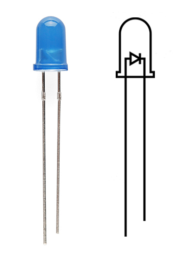
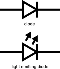
LEDs (that’s “ell-ee-dees”) are a particular type of diode that convert electrical energy into light. In fact, LED stands for “Light Emitting Diode.” (It does what it says on the tin!) And this is reflected in the similarity between the diode and LED schematic symbols:

alt text

In short, LEDs are like tiny lightbulbs. However, LEDs require a lot less power to light up by comparison. They’re also more energy efficient, so they don’t tend to get hot like conventional lightbulbs do (unless you’re really pumping power into them). This makes them ideal for mobile devices and other low-power applications. Don’t count them out of the high-power game, though. High-intensity LEDs have found their way into accent lighting, spotlights and even automotive headlights!

Are you getting the craving yet? The craving to put LEDs on everything? Good, stick with us and we’ll show you how!

Suggested Reading

Here are some other topics that will be discussed in this tutorial. If you are unfamiliar with any of them, please have a look at the respective tutorial before you go any further.

How to Use Them

alt text

So you’ve come to the sensible conclusion that you need to put LEDs on everything. We thought you’d come around. Let’s go over the rule book:

1) Polarity Matters

In electronics, polarity indicates whether a circuit component is symmetric or not. LEDs, being diodes, will only allow current to flow in one direction. And when there’s no current-flow, there’s no light. Luckily, this also means that you can’t break an LED by plugging it in backwards. Rather, it just won’t work.

alt text

The positive side of the LED is called the“anode” and is marked by having a longer “lead,” or leg. The other, negative side of the LED is called the “cathode.” Current flows from the anode to the cathode and never the opposite direction. A reversed LED can keep an entire circuit from operating properly by blocking current flow. So don’t freak out if adding an LED breaks your circuit. Try flipping it around.

2) Moar Current Equals Moar Light

The brightness of an LED is directly dependent on how much current it draws. That means two things. The first being that super bright LEDs drain batteries more quickly, because the extra brightness comes from the extra power being used. The second is that you can control the brightness of an LED by controlling the amount of current through it. But, setting the mood isn’t the only reason to cut back your current.

3) There is Such a Thing as Too Much Power

If you connect an LED directly to a current source it will try to dissipate as much power as it’s allowed to draw, and, like the tragic heroes of olde, it will destroy itself. That’s why it’s important to limit the amount of current flowing across the LED.

For this, we employ resistors. Resistors limit the flow of electrons in the circuit and protect the LED from trying to draw too much current. Don’t worry, it only takes a little basic math to determine the best resistor value to use. You can find out all about it in our resistor tutorial!

Don’t let all of this math scare you, it’s actually pretty hard to mess things up too badly. In the next section, we’ll go over how to make an LED circuit without getting your calculator.

LEDs Without Math

Before we talk about how to read a datasheet, let’s hook up some LEDs. After all, this is an LED tutorial, not a reading tutorial.

It’s also not a math tutorial, so we’ll give you a few rules of thumb for getting LEDs up and running. As you’ve probably put together from the info in the last section, you’ll need a battery, a resistor and an LED. We’re using a battery as our power source, because they’re easy to find and they can’t supply a dangerous amount of current.

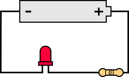
The basic template for an LED circuit is pretty simple, just connect your battery, resistor and LED in series. Like this:


alt text


A good resistor value for most LEDs is 330 Ohms. You can use the information from the last section to help you determine the exact value you need, but this is LEDs withoutmath… So, start by popping a 330 Ohm resistor into the above circuit and see what happens.

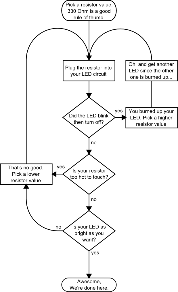
The interesting thing about resistors is that they’ll dissipate extra power as heat, so if you have a resistor that’s getting warm, you probably need to go with a smaller resistance. If your resistor is too small, however, you run the risk of burning out the LED! Given that you have a handful of LEDs and resistors to play with, here’s a flow chart to help you design your LED circuit by trial and error:


alt text


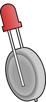
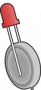
Another way to light up an LED is to just connect it to a coin cell battery! Since the coin cell can’t source enough current to damage the LED, you can connect them directly together! Just push a CR2032 coin cellbetween the leads of the LED. The long leg of the LED should be touching the side of the battery marked with a “+”. Now you can wrap some tape around the whole thing, add a magnet, and stick it to stuff! Yay for throwies!

alt text

Of course, if you’re not getting great results with the trial and error approach, you can always get out your calculator and math it up. Don’t worry, it’s not hard to calculate the best resistor value for your circuit. But before you can figure out the optimal resistor value, you’ll need to find the optimal current for your LED. For that we’ll need to report to the datasheet…

Get the Details

Don’t go plugging any strange LEDs into your circuits, that’s just not healthy. Get to know them first. And how better than to read the datasheet.

As an example we’ll peruse the datasheet for our Basic Red 5mm LED.

LED Current

Starting at the top and making our way down, the first thing we encounter is this charming table:

alt text

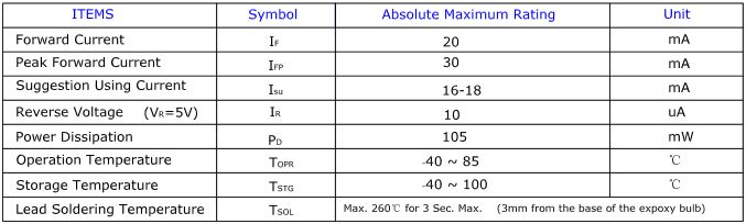
Ah, yes, but what does it all mean?

The first row in the table indicates how much current your LED will be able to handle continuously. In this case, you can give it 20mA or less, and it will shine its brightest at 20mA. The second row tells us what the maximum peak current should be for short bursts. This LED can handle short bumps to 30mA, but you don’t want to sustain that current for too long. This datasheet is even helpful enough to suggest a stable current range (in the third row from the top) of 16-18mA. That’s a good target number to help you make the resistor calculations we talked about.

The following few rows are of less importance for the purposes of this tutorial. The reverse voltage is a diode property that you shouldn’t have to worry about in most cases. The power dissipation is the amount of power in milliWatts that the LED can use before taking damage. This should work itself out as long as you keep the LED within its suggested voltage and current ratings.

LED Voltage

Let’s see what other kinds of tables they’ve put in here… Ah!

alt text

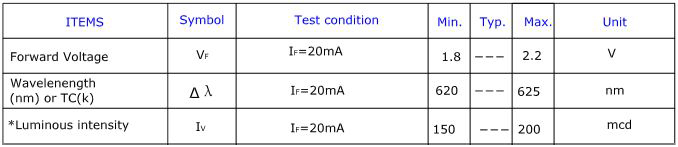
This is a useful little table! The first row tells us what the forward voltage drop across the LED will be. Forward voltage is a term that will come up a lot when working with LEDs. This number will help you decide how much voltage your circuit will need to supply to the LED. If you have more than one LED connected to a single power source, these numbers are really important because the forward voltage of all of the LEDs added together can’t exceed the supply voltage. We’ll talk about this more in-depth later in thedelving deeper section of this tutorial.

LED Wavelength

The second row on this table tells us the wavelength of the light. Wavelength is basically a very precise way of explaining what color the light is. There may be some variation in this number so the table gives us a minimum and a maximum. In this case it’s 620 to 625nm, which is just at the lower red end of the spectrum (620 to 750nm). Again, we’ll go over wavelength in more detail in thedelving deeper section.

LED Brightness

The last row (labeled “Luminous Intensity”) is a measure of how bright the LED can get. The unit mcd, or millicandela, is a standard unit for measuring the intensity of a light source. This LED has an maximum intensity of 200 mcd, which means it’s just bright enough to get your attention but not quite flashlight bright. At 200 mcd, this LED would make a good indicator.

Viewing Angle

alt text

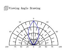
Next, we’ve got this fan-shaped graph that represents the viewing angle of the LED. Different styles of LEDs will incorporate lenses and reflectors to either concentrate most of the light in one place or spread it as widely as possible. Some LEDs are like floodlights that pump out photons in every direction; Others are so directional that you can’t tell they’re on unless you’re looking straight at them. To read the graph, imagine the LED is standing upright underneath it. The “spokes” on the graph represent the viewing angle. The circular lines represent the intensity by percent of maximum intensity. This LED has a pretty tight viewing angle. You can see that looking straight down at the LED is when it’s at its brightest, because at 0 degrees the blue lines intersect with the outermost circle. To get the 50% viewing angle, the angle at which the light is half as intense, follow the 50% circle around the graph until it intersects the blue line, then follow the nearest spoke out to read the angle. For this LED, the 50% viewing angle is about 20 degrees.

Dimensions

alt text

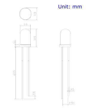
Finally, the mechanical drawing. This picture contains all of the measurements you’ll need to actually mount the LED in an enclosure! Notice that, like most LEDs, this one has a small flange at the bottom. That comes in handy when you want to mount it in a panel. Simply drill a hole the perfect size for the body of the LED, and the flange will keep it from falling through!

Now that you know how to decipher the datasheet, let’s see what kind of fancy LEDs you might encounter in the wild…

Types of LEDs

Congratulations, you know the basics! Maybe you’ve even gotten your hands on a few LEDs and started lighting stuff up, that’s awesome! How would you like to step up your blinky game? Let’s talk about makin’ it fancy.

Here’s the cast of characters:

alt text

RGB (Red-Green-Blue) LEDs are actually three LEDs in one! But that doesn’t mean it can only make three colors. Because red, green, and blue are the additive primary colors, you can control the intensity of each to create every color of the rainbow. Most RGB LEDs have four pins: one for each color and a common pin. On some, the common pin is the anode, and on others, it’s the cathode.


alt text

Some LEDs are smarter than others. Take theflashing LED, for example. Inside these LEDs, there’s actually an integrated circuit that allows the LED to blink without any outside controller. Simply power it up and watch it go! These are great for projects where you want a little bit more action but don’t have room for control circuitry. There are even RGB flashing LEDs that cycle through thousands of colors!


alt text

SMD LEDs aren’t so much a specific kind of LED but a package type. As electronics get smaller and smaller, manufacturers have figured out how to cram more components in a smaller space. SMD (Surface Mount Device) parts are tiny versions of their standard counterparts. SMD LEDs come in several sizes, from fairly large to smaller than a grain of rice! Because they’re so small, and have pads instead of legs, they’re not as easy to work with, but if you’re tight on space they might be just what the doctor ordered.


alt text

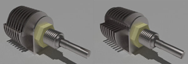
High-Power LEDs, from manufacturers like Luxeon and CREE, are crazy bright. Generally, an LED is considered High-Power if it can dissipate 1 Watt or more of power. These are the fancy LEDs that you find in really nice flashlights. Arrays of them can even be built for spotlights and automobile headlights. Because there’s so much power being pumped through the LED, these often require heatsinks. A heatsink is basically a chunk of heat conducting metal with lots of surface area whose job is to transfer as much waste heat into the surrounding air as possible. High-Power LEDs can generate so much waste heat that they’ll damage themselves without proper cooling. Don’t let the term “waste heat” fool you, though, these devices are still incredibly efficient compared to conventional bulbs.


alt text

There are even LEDs that emit light outside of the normal visible spectrum. You probably useInfrared LEDs every day, for instance. They’re used in things like TV remotes to send small pieces of information in the form of invisible light! On the opposite end of the spectrum you can also get Ultraviolet LEDs. Ultraviolet LEDs will make certain materials fluoresce, just like a blacklight! They’re also used for disinfecting surfaces, because many bacteria are sensitive to UV radiation.


With fancy LEDs like these at your disposal, there’s no excuse for leaving anything un-illuminated. However, if your thirst for LED knowledge hasn’t been slaked, then read on, and we’ll get into the nitty-gritty on LEDs, color, and luminous intensity!

Delving Deeper

So you’ve graduated from LEDs 101 and you want more? Oh, don’t worry, we’ve got more. Let’s start with the science behind what makes LEDs tick… err… blink. We’ve already mentioned that LEDs are a special kind of diode, but let’s delve a little deeper into exactly what that means:

What we call an LED is really the LED and the packaging together, but the LED itself is actually tiny! It’s a chip of semiconductor material that’s doped with impurities which creates a boundary for charge carriers. When current flows into the semi-conductor, it jumps from one side of this boundary to the other, releasing energy in the process. In most diodes that energy leaves as heat, but in LEDs that energy is dissipated as light!

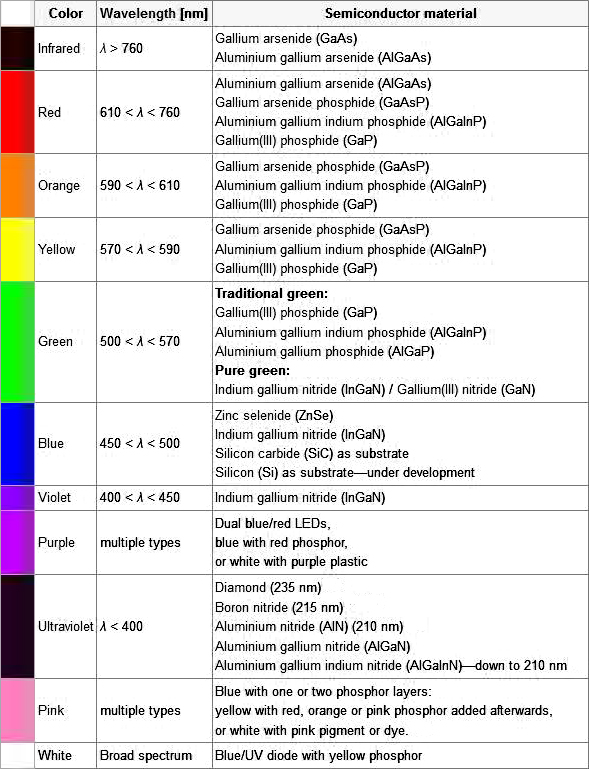
The wavelength of light, and therefore the color, depends on the type of semiconductor material used to make the diode. That’s because the energy band structure of semiconductors differs between materials, so photons are emitted with differing frequencies. Here’s a table of common LED semiconductors by frequency:

alt text

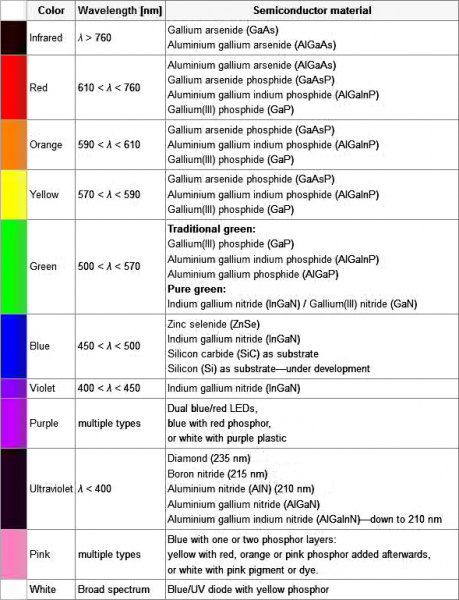
Truncated table of semiconductor materials by color. The full table is available on the Wikipedia entry for “LED”

While the wavelength of the light depends on the band gap of the semiconductor, the intensity depends on the amount of power being pushed through the diode. We talked about luminous intensity a little bit in a previous section, but there’s more to it than just putting a number on how bright something looks.

The unit for measuring luminous intensity is called the candela, although when you’re talking about the intensity of a single LED you’re usually in the millicandela range. The interesting thing about this unit is that it isn’t really a measure of the amount of light energy, but an actual measure of “brightness”. This is achieved by taking the power emitted in a particular direction and weighting that number by the luminosity function of the light. The human eye is more sensitive to some wavelengths of light than others, and the luminosity function is a standardized model that accounts for that sensitivity.

The luminous intesity of LEDs can range from the tens to the tens-of-thousands of millicandela. The power light on your TV is probably about 100 mcd, whereas a good flashlight might be 20,000 mcd. Looking straight into anything brighter than a few thousand millicandela can be painful; don’t try it.

Forward Voltage Drop

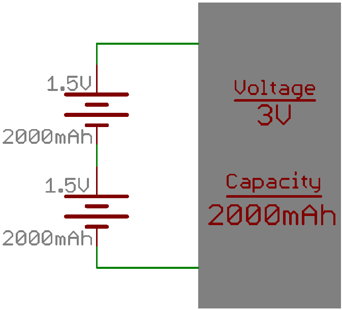
Oh, I also promised that we’d talk about the concept of Forward Voltage Drop. Remember when we were looking at the datasheet and I mentioned that the Forward Voltage of all of your LEDs added together can’t exceed your system voltage? This is because every component in your circuit has to share the voltage, and the amount of voltage that every part uses together will always equal the amount that’s available. This is calledKirchhoff’s Voltage Law. So if you have a 5V power supply and each of your LEDs have a forward voltage drop of 2.4V then you can’t power more than two at a time.

Kirchhoff’s Laws also come in handy when you want to approximate the voltage across a given part based on the Forward Voltage of other parts. For instance, in the example I just gave there’s a 5V supply and 2 LEDs with a 2.4V Forward Voltage Drop each. Of course we would want to include a current limiting resistor, right? How would you find out the voltage across that resistor? It’s easy:

5 (System Voltage) = 2.4 (LED 1) + 2.4 (LED 2) + Resistor

5 = 4.8 + Resistor

Resistor = 5 – 4.8

Resistor = 0.2

So there is .2V across the resistor! This is a simplified example and it isn’t always this easy, but hopefully this gives you an idea of why Forward Voltage Drop is important. Using the voltage number you derive from Kirchhoff’s Laws you can also do things like determine the current across a component using Ohm’s Law. In short, you want your system voltage equal to the expected forward voltage of your combined circuit components

How to Power a Project

Overview

This tutorial will cover the various ways you can power your electronic projects. It will go into some detail about voltage and current considerations you may want to make. It will also go into the extra considerations you have to make if your project is mobile/remote or, in other words, not going to be sitting next to a wall power outlet.

If this is truly your first electronic project, you have the option of reading through this tutorial or sticking with the recommended supply for the project or development board of your choice. The SparkFun Inventor’s Kit contains the USB cable you need for power and works fine for all the projects in the kit as well as many more advanced projects. If you’re feeling overwhelmed, that kit is the best place to start.

Suggested Reading

Here are related tutorials you may want to check out before reading this one:

Ways to Power a Project

Here are some of the most methods used for powering a project:

  • AC to DC power supplies (like a computer or laptop would use)
  • Variable DC bench power supply
  • Batteries
  • Via a USB cable

Left to Right: AC/DC power adapter, bench supply, battery, USB cable

Four common ways to supply power to your project

Which option should I pick to power my project?

The answer to this question largely depends on your project specific requirements.

If you’re starting off with the SparkFun Inventor’s Kit or another basic development board, you will likely just need a USB cable. The Arduino Uno is an example that requires only a USB A to B cable to supply the power to run the example circuits in the kit.

If you’re in the business of building projects and testing circuits regularly, acquiring avariable DC bench power supply is highly recommended. This will allow you to set the voltage to a specific value depending on what you need for your project. It also buys you some protection as you can set a maximum current allowed. Then, if there is a short circuitin your project, the bench supply will shut down hopefully preventing harm to some components in your project.

A specific AC to DC power supply is often used after a circuit is proven. This option is also great if you often use the same development board again and again in your projects. These wall adapters usually have a set voltage and current output, so it’s important to make sure that the adapter you choose has the correct specifications as the project you will be powering and to not exceed those specifications.

If you want your project to be mobile or based in a remote location away from where you can gather AC wall power from the grid, batteries are the answer you’re looking for. Batteries come in a huge variety so be sure to check out the later parts of this tutorial so you can figure out precisely what to choose. Common choices include rechargeable NiMH AA’s andlithium polymer ion.

Voltage/Current Considerations

How much voltage do I need for project X?

This depends largely on the circuit, so there is no easy answer to this question. However, most microprocessor development boards like the Arduino Uno have a voltage regulator on board. This allows us to supply a voltage in a specified range above the regulated voltage. A lot of microprocessors and IC’s on development boards run at 3.3 or 5 Volts but have voltage regulators that can handle anywhere from 6V to 12V.

The power comes from a power supply and is then regulated closely by a voltage regulator so that each chip is powered at a consistent voltage even when the current draw may fluctuate at different times. Here at SparkFun, we use 9V power supplies for many of our products that operate in the 3.3V to 5V range. However, to verify what voltages are safe, it is recommended that you check the datasheet for the voltage regulator on the development board to see what voltage range is recommended by the manufacturer.

How much current do I need for project X?

This question also depends on the development board and microprocessor you’re using as well as what circuits you plan on connecting to it. If your power supply cannot give you the amount of juice the project needs, the circuit may start acting in a strange, unpredictable way. This is also known as a brown-out.

As with voltage, it’s recommended to check the datasheets and estimate what the different bits and pieces of the circuit might need. It’s also better practice to round up and assume your circuit will need more current than to not provide enough current. If your circuit includes elements that require massive amounts of current, like motors or large amounts of LEDs, you may need a large supply or even separate supplies for the microprocessor and the extra motors. Again, it’s always in your best interest to get a power supply rated for a higher current and not use the extra than to have a supply that can’t provide enough.

Have no idea how much current your project draws?

Once you’ve been playing with circuits for a while, it will be easier to estimate the amount of current your project requires. However, the common ways to figure it out experimentally are to either use a variable DC power supply that has a readout for current or to use adigital multimeter to measure the current going to your circuit while it’s running. If you don’t know how to measure current with a multimeter, please see our multimeter tutorial.

For your voltage and current measuring needs

Digital Multimeter

We highly recommend having a DMM in your electronics toolbox. It’s great for measuring current or voltage.

Connections

How do I connect my battery or power supply to my circuit?

There are many ways to actually connect a power supply to your project.

Left to right: banana jacks, wire hookup, barrel jack, battery case, JST

Common ways to connect a power to your circuit

Variable benchtop power supplies commonly connect to circuits using banana jacks orwires directly. These are also similar to the connectors found on the multimeter probe cables.

Many projects are built on a breadboard first, as a prototype, before they become a final product. There are numerous ways to power your breadboard circuit, many of them involving a the same connectors mentioned here.

Once a project is past the prototyping phase, it will usually end up on a PCB. One of the most common power connectors used on a finished PCB, in both consumer electronics and hobby electronics alike, is the barrel connector, also know as a barrel jack. These can vary in size, but they all function the same and provide a simply, reliable way to power your project.

Batteries are generally held in a case that holds the batteries and connects the the circuit via wires or a barrel jack. Some batteries like Lithium Polymer Ion batteries often use a JST connector.

To learn more about different power connectors, please see our connectors tutorial.

Remote/Mobile Power

Which battery should I choose?

When you’re powering a remote circuit, the same issues of finding a battery that delivers the proper voltage and current still apply. Battery life, or capacity, is a measure of total charge the battery contains. The capacity of a battery is usually rated in ampere-hours (Ah) or milliampere-hours (mAh), and it tells you how many amps a fully charged battery can supply over a period of one hour. For example, a 2000mAh battery can supply up to 2A (2000mA) for one hour.

Battery size, shape, and weight is also something to consider when making your project mobile, especially if it’s going to be on something that flies like a small quad-copter. You can get a rough idea of the variety by visiting this wikipedia list. Learn more about battery types in our battery technology tutorial.

Batteries in series and parallel

You can add batteries in series or parallel to produce the desired voltage and current needed for your project. When two or more batteries are placed in series, the voltages of the batteries are added together. For example, lead-acid car batteries are actually made out of six single-cell lead acid batteries tied together in series; the six 2.1V cells add up to produce 12.6V. When tying two batteries in series, it’s recommended that they be of the same chemistry. Also be wary of charging batteries in series as many chargers are limited to single-cell charging.

alt text

When you connect two or more batteries inparallel, the capacities add. For example, four AA batteries connected in parallel will still produce 1.5V, however the capacity of the batteries will be quadrupled.

alt text

How much battery capacity do I need for my project?

This question is easier to answer once you have determined the amount of current that your circuit normally draws. In the following example, we will use estimation. However, it is encouraged that you measure current draw of your circuit using a Digital Multimeter to get accurate results.

As an example, let’s start with a circuit, estimate its current output, then select a battery and calculate how long it the circuit will run on battery power. Let’s choose aATmega 328 microcontroller to be our brains for the circuit. It draws about 20mA under normal conditions. Let’s now connect threered LED’s and the standard 330 ohm current limiting resistors to digital I/O pins of the microcontroller. In that configuration, each LED added makes the circuit draw about 10mA more current. Now let’s connect twoMicro Metal motors to the microcontroller as well. Each one of these uses approximately 25mA when turned on. Our total possible current draw is now:

Calculating Circuit Current Draw

Let’s choose a standard alkaline AA battery for this because it has more than enough current capability (up to 1A), has a decent battery capacity (usually in the range of 1.5 Ah to 2.5Ah), and is very common. We’ll assume the average is 2Ah for this example. The downside to using a AA is it only has a 1.5V output, and, since the rest of our components will run on 5V, we need to step up the voltage. We can use this 5V step-up breakout to get the voltage we need, or we can use three AA batteries in series to get us close to the voltage we need. Three AA’s in series gives us a voltage of 4.5 V (3 times 1.5V). You could also add another battery for a total of 6V and regulate the voltage down to what your circuit requires.

To calculate how long a circuit will last on battery power, we use the following equation:

The equation for calculating battery life

For a circuit powered by 3 AA’s in parallel that’s connected to a circuit with a constant 100mA current draw, this translates to:

We would ideally get 60 hours of battery life out of these three alkaline AA’s in this parallel configuration. However, it’s good practice to ‘derate’ batteries, which means to assume you’re going to get less than ideal battery life. Let’s conservatively say that we’ll get 75% of the ideal battery life, and therefore about 45 hours of battery life for our project.

Battery life can also vary based on the actual current draw amount. Here’s a graph from an Energizer AA battery showing its expected battery life based on constant current draw.

Energizer AA E91 Specifications

Energizer AA, Current vs Battery Life

This is just one of the numerous configurations you could use to power your project remotley.

Design a site like this with WordPress.com
Get started