Category Archives: Uncategorized

3 Reasons For Increased Efficiency Loss In Rewound Motors

The loss in efficiency of rewound motors

Approximately 300,000 motors are rewound in the UK every year, with an average rating of about 12 kW, so the efficiency of rewound motors is extremely important. The loss in efficiency on rewinding depends on the techniques, processes and skill used to perform the rewind, and is usually between 1 and 2%.

The reasons for increased loss are discussed below. If the choice is between rewinding a standard efficiency motor or purchasing a new high efficiency motor, the difference in efficiency will be 4 to 5% at full load in favour of the high efficiency motor, which will also have a much longer service life.

Generally speaking, there are three factors affecting the efficiency of rewound motors, and let’s talk about each of them //

1. Increase in Iron Losses

An increase in the iron losses can be caused by //

  • Mechanical damage to the core
  • Thermal damage to the core
  • Electromagnetic changes

Mechanical stress in the core will increase the hysteresis loss, as might happen if the core is fitted into a new frame with an undersized bore. The practice of hammering stator teeth back into place after stripping will result in increased hysteresis locally as a result of the residual stress.

Eddy current loss will increase if the insulation between adjacent laminations is damaged, for example by burring together by filing or by accidental impact.

Steel laminations being destroyed
Steel laminations being destroyed. The vertical slots were originally in straight lines, not broken up as shown. Since their edges are sharp, they can easily cut through the stator winding insulation and short them together, creating an electric heating circuit instead of a motor. (photo credit: nlcpr.com)


The stator tooth tips and rotor surface are the most vulnerable,since both carry high frequency harmonic fluxes. Skimming to remove damage is rarely acceptable because the air gap is increased and efficiency reduced.

Thermal damage to the oxide or varnish insulation between the laminations is normally regarded as the usual cause of increased iron loss following a rewind. New work in which the increased loss after rewind under carefully controlled conditions for a number of motors was measured has shown that for conventional steels the temperature should not exceed 380°C. Losses increase very rapidly at higher temperatures.

The very highest efficiency motors use thin laminations of high quality steel, coated with a microfilm of varnish and these were found to exhibit no increased loss over the test range of 350 – 400°C.

Most motors are designed to run with flux densities in the stator and rotor core just over the knee of the magnetisation curve. If the winding characteristics are changed after rewind, for example if the number of turns are reduced, the flux density and hence the loss will increase.

Saturation curve of a DC generator


2. Copper Loss

Stator copper loss is the largest loss (at full load) in most induction motors. The winding pattern may be changed during rewinding to simplify the process, and in doing so the repairer must consider the effect on flux density and resistance.

Of load losses, stator copper losses (also referred to as I2R losses) are caused by heating from the current flow through the resistance of the stator winding. Techniques for reducing these losses include optimizing the stator slot design. Rotor losses are caused by rotor currents and iron losses.

These losses are reduced for example by increasing the size of the conductive bars and end rings to produce lower resistance. Stray load losses are the result of leakage fluxes induced by load currents. These can be decreased by improving slot geometry of rewound motors.

Full considerations of these losses are very complex, and are beyond the scope of this article. Full details can be found in this reference.

3. Mechanical Considerations

The concentricity of rotor and stator is very important. It is common practice to metal spray shafts or bearing housingswhich have been damaged in service. This is acceptable only if special care is taken to preserve concentricity – errors which result in a minimum to maximum gap ratio greater than 1:1.25 will adversely affect efficiency

Polarity

What is Polarity?

In the realm of electronics, polarity indicates whether a circuit component is symmetric or not. A non-polarized component – a partwithout polarity – can be connected in any direction and still function the way it’s supposed to function. A symmetric component rarely has more than two terminals, and every terminal on the component is equivalent. You can connect a non-polarized component in any direction, and it’ll function just the same.

polarized component – a part with polarity – can only be connected to a circuit in one direction. A polarized component might have two, twenty, or even two-hundred pins, and each one has a unique function and/or position. If a polarized component was connected to a circuit incorrectly, at best it won’t work as intended. At worst, an incorrectly connected polarized component will smoke, spark, and be one very dead part.

alt text

An assortment of polarized components: batteries, integrated circuits, transistors, voltage regulators, electrolytic capacitors, and diodes, among others.

Polarity is a very important concept, especially when it comes to physically building circuits. Whether you’re plugging parts into a breadboard, soldering them to a PCB, or sewing them into an e-textile project, it’s critical to be able to identify polarized components and to connect them in the correct direction. So that’s what we’re here for! In this tutorial we’ll discuss which components do and don’t have polarity, how to identify component polarity, and how to test some components for polarity.

Consider Reading

If your head’s not swimming yet, it’s probably safe to read through the rest of this tutorial. Polarity is a concept which builds on some lower-level electronics concepts and reinforces a few others. If you haven’t already, consider checking out some of the below tutorials, before you read through this one.

Diode and LED Polarity

Diodes only allow current to flow in one direction, and they’re always polarized. A diode has two terminals. The positive side is called the anode, and the negative one is called the cathode.

Diode circuit symbol, with anode/cathode labeled

The diode circuit symbol, with the anode and cathode marked.

Current through a diode can only flow from the anode to the cathode, which would explain why it’s important for a diode to be connected in the correct direction. Physically, every diode should have some sort of indication for either the anode or cathode pin. Usually the diode will have a line near the cathode pin, which matches the vertical line in the diode circuit symbol.

Below are a few examples of diodes. The top diode, a 1N4001 rectifier, has a grey ring near the cathode. Below that, a 1N4148 signal diode uses a black ring to mark the cathode. At the bottom are a couple surface mount diodes, each of which use a line to mark which pin is the cathode.

Some real diodes and their cathode markings

Notice the lines on each device, denoting the Cathode side, which match the line in the symbol above.

LEDs

LED stands for light-emitting diode, which means that much like their diode cousins, they’re polarized. There are a handful of identifiers for finding the positive and negative pins on an LED. You can try to find the longer leg, which should indicate the positive, anode pin.

Or, if someone’s trimmed the legs, try finding the flat edge on the LED’s outer casing. The pin nearest the flat edge will be the negative, cathode pin.

LED polarity indicators

There might be other indicators as well. SMD diodes have a range of anode/cathode identifiers. Sometimes it’s easiest to just use a multimeter to test for polarity. Turn the multimeter to the diode setting (usually indicated by a diode symbol), and touch each probe to one of the LED terminals. If the LED lights up, the positive probe is touching the anode, and the negative probe is touching the cathode. If it doesn’t light up, try swapping the probes around.

LED polarity test with multimeter

The polarity of a tiny, yellow, surface-mount LED is tested with a multimeter. If the positive lead touches the anode and negative touches the cathode, the LED should light up.


Diodes certainly aren’t the only polarized component. There are tons of parts out there that won’t work if connected incorrectly. Next we’ll discuss some of the other common polarized components, beginning with integrated circuits.

Integrated Circuit Polarity

Integrated circuits (ICs) might have eight pins or eighty pins, and each pin on an IC has a unique function and position. It’s very important to keep polarity straight with ICs. There’s a good chance they’ll smoke, melt, and be ruined if connected incorrectly.

Through-hole ICs usually come in a dual-inline package (DIP) – two rows of pins, each spaced by 0.1″ wide enough to straddle the center of a breadboard. DIP ICs usually have anotch to indicate which of the many pins is the first. If not a notch, the IC might have an etched dot in the casing near pin 1.

IC Polarity Labeled

An IC with both a dot and a notch to indicate polarity. Sometimes you get both, sometimes you only get one or the other.

For all IC packages, pin numbers increase sequentially as you move counter-clockwise away from pin 1.

MCP3002 pin-numbering

Surface-mount ICs might come in QFN, SOIC, SSOP, or a number of other form-factors. These ICs will usually have a dot near pin 1.

ATmega32U4

An ATmega32U4 in a TQFP package, next to the datasheet pinout.

Electrolytic Capacitors

Not all capacitors are polarized, but when they are, it’s very important not to mix their polarity up.

Ceramic capacitors – the small (1µF and less), commonly yellow guys – are notpolarized. You can stick those in either way.

Ceramic caps -- NOT polarized

Through-hole and SMD 0.1µF ceramic capacitors. These are NOT polarized.

Electrolytic caps (they’ve got electrolytes), which look like little tin cans, are polarized. The negative pin of the cap is usually indicated by a “-” marking, and/or a colored strip along the can. They might also have alonger positive leg.

Below are 10µF (left) and a 1mF electrolytic capacitors, each of which has a dash symbol to mark the negative leg, as well as a longer positive leg.

Electrolytic Capacitors

Applying a negative voltage for an extended period to an electrolytic capacitor results in a briefly exciting, but catastrophic, failure. They’ll make a pop, and the top of the cap will either swell or burst open. From then on the cap will be as good as dead, acting like a short circuit.

Other Polarized Components

Batteries and Power Supplies

Getting polarity right in your circuit all starts and ends with getting the power supplyconnected correctly. Whether you’re project’s getting power from a wall-wart or a LiPo battery, it’s critical to make sure you don’t accidently connect them backwards and apply9V or 4.2V to your project accidently.

Anyone that’s ever replaced batteries knows how to find their polarity. Most batteries will indicate the positive and negative terminals with a “+” or “-” symbol. Other times it might be red wire for positive and a black wire for negative.

Assorted batteries, each have some way to identify polarity

An assortment of batteries. Lithium polymer,coin cell9V alkalineAA alkaline, and AA NiMH. Each has some way to represent positive or negative terminals.

Power supplies usually have a standardizedconnector, which should usually have polarity itself. A barrel jack, for example, has two conductors: outer and inner; the inner/center conductor is usually the positive terminal. Other connectors, like a JST, are keyed so you just can’t connect them backwards.

Power supply connector

For extra protection against reversing power supply polarity, you can add reverse polarity protection using a diode, or a MOSFET.

Transistors, MOSFETs, and Voltage Regulators

These (traditionally) three-terminal, polarized components are lumped together because they share similar package types. Through-hole transistors, MOSFETs, and voltage regulators commonly come in a TO-92 or TO-220 package, seen below. To find which pin is which, look for the flat edge on the TO-92 package or the metal heatsink on the TO-220, and match that up to the pin-out in the datasheet.

TO-92 transistor and TO-220 Vreg

Above, a 2N3904 transistor in a TO-92 package, note the curved and straight edges. A 3.3V regulator in a TO-220 package, note the metal heatsink on the back.

Etc.

This is just the tip of the polarized-component iceberg. Even non-polarized components, likeresistors, can come in polarized packages. A resistor pack – a grouping of five-or-so pre-arranged resistors – is one such example.

Resistor pack

A polarized resistor pack. An array of five 330Ω resistors, all tied together at one end. The dot represents the first, common pin.

Fortunately, every polarized component should have some way to inform you which pin is which. Be sure to always read the datasheets, and check the case for dots or other markers.

Best practice for using surge protective devices (SPDs) and RCD together

Surge protective devices (SPDs) and RCDs

Where the power distribution system incorporates RCDs transient activity could cause RCDs to operate and hence loss of supply. Surge protective devices (SPDs) should wherever possible be installed upstream of RCD to prevent unwanted tripping caused by transient overvoltages.

Where surge protective devices are installed in accordance with BS 7671534.2.1 and are on the load side of a residual current device, an RCD having an immunity to surge currents of at least 3 kA 8/20, shall be used.

IMPORTANT NOTES // S type RCDs satisfy this requirement. In the case of surge currents higher than 3 kA 8/20, the RCD may trip causing interruption of the power supply.

If the SPD is installed downstream of the RCD, the RCD should be of the time delayed type with an immunity to surge currents of at least 3kA 8/20. Section 534.2.2 of BS 7671 details the minimum SPD connection requirements (based on the SPD modes of protection) at the origin of the installation (typically a Type 1 SPD).

In case you are not familiar with surge protective devices operation and types, you better read firstthe basics of surge protective devices.


SPD connection type 1 (CT1)

An SPD configuration based on connection type 1 (CT1) is for TN-C-S or TN-S earthing arrangements as well the TT earthing arrangement where the SPD is fitted downstream of the RCD.

Surge protective devices (SPDs) installed on load side of RCD
Figure 1 – Surge protective devices (SPDs) installed on load side of RCD (click to expand scheme)

In general, TT systems require special attention because they normally have higher earth impedances which reduces earth fault currents and increases the disconnection times of Overcurrent Protective Devices – OCPDs.

Therefore in order to meet the requirements for safe disconnection times, RCDs are used forearth fault protection.


SPD connection type 2 (CT1)

An SPD configuration based on connection type 2 (CT2) is required on aTT earth arrangement if the SPD is upstream of the RCD. The RCD being downstream of the SPD would not operate should the SPD become defective.

Surge protective devices (SPDs) installed on supply side of RCD
Figure 2 – Surge protective devices (SPDs) installed on supply side of RCD (click to expand scheme)

The SPD arrangement here is configured such that the SPDs are applied between the live conductors (live to neutral) rather than between live conductors and the protective conductor.

Should the SPD become defective it would therefore create a short circuit current rather than an earth fault current and as such would ensure that the overcurrent protective devices (OCPDs) in-line with the SPD safely operates within the required disconnection time.

A higher energy SPD is usedbetween neutral and the protective conductor. This higher energy SPD (typically a spark-gap for a Type 1 SPD) is required as lightning currents arise towards the protective conductor and as such this higher energy SPD sees up to 4 times the surge current of the SPDs connected between the live conductors.

Clause 534.2.3.4.3 therefore advises that the SPD between neutral and the protective conductor is rated at 4 times the magnitude of the SPD between the live conductors.

Therefore, only if the impulse current Iimp cannot be calculated, 534.2.3.4.3 advises that the minimum value Iimp for an SPD between neutral and the protective conductor is 50kA 10/350 for a 3 phase CT2 installation, 4 times 12.5kA 10/350 of the SPDs between thelive conductors.

The CT2 SPD configuration is often referred the ‘3+1’ arrangement for a 3 phase supply.


SPDs and TN-C-S earth configurations

The minimum SPD connection requirements at or near the origin of the installation for a TN-C-S system requires further clarification as Section 534 of BS 7671 illustrates (see Figure 3 below) a Type 1 SPD being required between the live and PE conductors – the same as required for a TN-S system.

Installation of Types 1, 2 and 3 SPDs, for example in TN-C-S systems
Figure 3 – Installation of Types 1, 2 and 3 SPDs, for example in TN-C-S systems (click to expand scheme)

The term ‘at or near the origin of the installation’ creates ambiguity given the fact that the word ‘near’ is not defined. From a technical point of view, if SPDs are applied within a 0.5m distance of the PEN split to separate N and PE, there is no need to have an SPD protection mode between N and PE as shown in the figure.

If BS 7671 would allow the application of SPDs to the TN-C side (utility side) of the TN-C-S system (observed in some parts of Europe), then it may be possible to install SPDs within 0.5m of the PEN split to N and PE and omit the N to PE SPD protection mode.

However as SPDs can only be applied the TN-S side (consumer side) of the TN-C-S system, and given SPDs are typically installed at the main distribution board, the distance between the SPD installation point and the PEN split will almost always begreater than 0.5 m, so there is a need to have an SPD between N and PE as required for a TN-S system.

As Type 1 SPDs are specifically installed to prevent the risk of loss of human life (to BS EN62305) through dangerous sparking which could present a fire hazard for example, in the interests of safety alone, the engineering judgement is that an SPD should be fitted between N and PE for a TN-C-S system as it would in a TN-S system.

In summary, as far as Section 534 is concerned, TN-C-S systems are treated the same as TN-S systems for the selection and installation of SPDs.


The basics of surge protection devices

A Surge Protection Device (SPDs)is a component of the electrical installation protection system. This device is connected to the power supply in parallel with the loads (circuits) that it is intended to protect (see Figure 4). It can also be used at all levels of the power supply network.

This is the most commonly used and most practical type of overvoltage protection.


Principle of Surge Protection Operation

SPDs are designed to limit transient overvoltages due to lightning or switching and divert the associated surge currents to earth, so as to limit these overvoltages to levels that are unlikely to damage the electrical installation or equipment.

Principle of protection system in parallel
Figure 4 – Principle of protection system in parallel

Types of surge protection devices

There are three types of SPD according to international standards:


Type 1 SPD

Protection against transient overvoltages due to direct lightning strokes. The Type 1 SPD is recommended to protect electrical installations against partial lightning currents caused by direct lightning strokes. It can discharge the voltage from lightning spreading from the earth conductor to the network conductors.

Type 1 SPD is characterised by a10/350µs current wave.

Three types of SPD according to international standards
Figure 5 – Three types of SPD according to international standards

Type 2 SPD

Protection against transient overvoltages due to switching and indirect lightning strokes. The Type 2 SPD is the main protection system for all low voltage electrical installations. Installed in each electrical switchboard, it prevents the spread of overvoltages in the electrical installations and protects the loads.

Type 2 SPD is characterised by an8/20µs current wave.


Type 3 SPD

Type 3 SPD is used for local protection for sensitive loads. These SPDs have a low discharge capacity. They must therefore only be installed as a supplement to Type 2 SPD and in the vicinity of sensitive loads. They are widely available as hard wired’ devices (frequently combined with Type 2 SPDs for use in fixed installations).

However they are also incorporated in:

  1. Surge protected socket outlets
  2. Surge protected portable socket outlets
  3. Telecoms and Data protection

Reference // BEAMA Guide to Surge Protection Devices (SPDs): selection, application and theory

What is the difference between MCB, MCCB, ELCB, and RCCB

MCB (Miniature Circuit Breaker)

MCB (Miniature Circuit Breaker)

Characteristics
  • Rated current not more than 100 A.
  • Trip characteristics normally not adjustable.
  • Thermal or thermal-magnetic operation.

Top

MCCB (Moulded Case Circuit Breaker)

MCCB (Moulded Case Circuit Breaker)

Characteristics
  • Rated current up to 1000 A.
  • Trip current may be adjustable.
  • Thermal or thermal-magnetic operation.

Top

Air Circuit Breaker

Characteristics
  • Rated current up to 10,000 A.
  • Trip characteristics often fully adjustable including configurable trip thresholds and delays.
  • Usually electronically controlled—some models are microprocessor controlled.
  • Often used for main power distribution in large industrial plant, where the breakers are arranged in draw-out enclosures for ease of maintenance.

Top

Vacuum Circuit Breaker

Characteristics
  • With rated current up to 3000 A,
  • These breakers interrupt the arc in a vacuum bottle.
  • These can also be applied at up to 35,000 V. Vacuum circuit breakers tend to have longer life expectancies between overhaul than do air circuit breakers.

Top

RCD (Residual Current Device / RCCB(Residual Current Circuit Breaker)

RCCB - Residual Current Circuit Breaker

Characteristics
  • Phase (line) and Neutral both wires connected through RCD.
  • It trips the circuit when there is earth fault current.
  • The amount of current flows through the phase (line) should return through neutral .
  • It detects by RCD. any mismatch between two currents flowing through phase and neutral detect by -RCD and trip the circuit within 30Miliseconed.
  • If a house has an earth system connected to an earth rod and not the main incoming cable, then it must have all circuits protected by an RCD (because u mite not be able to get enough fault current to trip a MCB)
  • RCDs are an extremely effective form of shock protection

The most widely used are 30 mA (milliamp) and 100 mA devices. A current flow of 30 mA (or 0.03 amps) is sufficiently small that it makes it very difficult to receive a dangerous shock. Even 100 mA is a relatively small figure when compared to the current that may flow in an earth fault without such protection (hundred of amps)

A 300/500 mA RCCB may be used where only fire protection is required. eg., on lighting circuits, where the risk of electric shock is small.

  Limitation of RCCB

  • Standard electromechanical RCCBs are designed to operate on normal supply waveformsand cannot be guaranteed to operate where none standard waveforms are generated by loads. The most common is the half wave rectified waveform sometimes called pulsating dc generated by speed control devices, semi conductors, computers and even dimmers.
  • Specially modified RCCBs are available which will operate on normal ac and pulsating dc.
  • RCDs don’t offer protection against current overloads: RCDs detect an imbalance in the live and neutral currents. A current overload, however large, cannot be detected. It is a frequent cause of problems with novices to replace an MCB in a fuse box with an RCD. This may be done in an attempt to increase shock protection. If a live-neutral fault occurs (a short circuit, or an overload), the RCD won’t trip, and may be damaged. In practice, the main MCB for the premises will probably trip, or the service fuse, so the situation is unlikely to lead to catastrophe; but it may be inconvenient.
  • It is now possible to get an MCB and and RCD in a single unit, called an RCBO (see below). Replacing an MCB with an RCBO of the same rating is generally safe.
  • Nuisance tripping of RCCB:Sudden changes in electrical load can cause a small, brief current flow to earth, especially in old appliances. RCDs are very sensitive and operate very quickly; they may well trip when the motor of an old freezer switches off. Some equipment is notoriously `leaky’, that is, generate a small, constant current flow to earth. Some types of computer equipment, and large television sets, are widely reported to cause problems.
  • RCD will not protect against a socket outlet being wired with its live and neutral terminals the wrong way round.
  • RCD will not protect against the overheating that results when conductors are not properly screwed into their terminals.
  • RCD will not protect against live-neutral shocks, because the current in the live and neutral is balanced. So if you touch live and neutral conductors at the same time (e.g., both terminals of a light fitting), you may still get a nasty shock.


ELCB (Earth Leakage Circuit Breaker)

ELCB (Earth Leakage Circuit Breaker)

Characteristics
  • Phase (line), Neutral and Earth wire connected through ELCB.
  • ELCB is working based on Earth leakage current.
  • Operating Time of ELCB: 
    • The safest limit of Current which Human Body can withstand is 30ma sec.
    • Suppose Human Body Resistance is 500Ω and Voltage to ground is 230 Volt.
    • The Body current will be 500/230=460mA.
    • Hence ELCB must be operated in  30maSec/460mA = 0.65msec

Top

RCBO (Residual Circuit Breaker with OverLoad)

  • It is possible to get a combined MCB and RCCB in one device (Residual Current Breaker with Overload RCBO), the principals are the same, but more styles of disconnection are fitted into one package

Top

Difference between ELCB and RCCB

  • ELCB is the old name and often refers to voltage operated devices that are no longer available and it is advised you replace them if you find one.
  • RCCB or RCD is the new name that specifies current operated (hence the new name to distinguish from voltage operated).
  • The new RCCB is best because it will detect any earth fault. The voltage type only detects earth faults that flow back through the main earth wire so this is why they stopped being used.
  • The easy way to tell an old voltage operated trip is to look for the main earth wire connected through it.
  • RCCB will only have the line and neutral connections.
  • ELCB is working based on Earth leakage current. But RCCB is not having sensing or connectivity of Earth, because fundamentally Phase current is equal to the neutral current in single phase. That’s why RCCB can trip when the both currents are deferent and it withstand up to both the currents are same. Both the neutral and phase currents are different that means current is flowing through the Earth.
  • Finally both are working for same, but the thing is connectivity is difference.
  • RCD does not necessarily require an earth connection itself (it monitors only the live and neutral).In addition it detects current flows to earth even in equipment without an earth of its own.
  • This means that an RCD will continue to give shock protection in equipment that has a faulty earth. It is these properties that have made the RCD more popular than its rivals. For example, earth-leakage circuit breakers (ELCBs) were widely used about ten years ago. These devices measured the voltage on the earth conductor; if this voltage was not zero this indicated a current leakage to earth. The problem is that ELCBs need a sound earth connection, as does the equipment it protects. As a result, the use of ELCBs is no longer recommended.

Top

MCB Selection

  • The first characteristic is the overload which is intended to prevent the accidental overloading of the cable in a no fault situation. The speed of the MCB tripping will vary with the degree of the overload. This is usually achieved by the use of a thermal device in the MCB.
  • The second characteristic is the magnetic fault protection, which is intended to operate when the fault reaches a predetermined level and to trip the MCB within one tenth of a second. The level of this magnetic trip gives the MCB its type characteristic as follows:

    Type Tripping Current Operating Time
    Type B 3 To 5 time full load current 0.04 To 13 Sec
    Type C 5 To 10 times full load current 0.04 To 5 Sec
    Type D 10 To 20 times full load current 0.04 To 3 Sec
  • The third characteristic is the short circuit protection, which is intended to protect against heavy faults maybe in thousands of amps caused by short circuit faults.
  • The capability of the MCB to operate under these conditions gives its short circuit rating in Kilo amps (KA). In general for consumer units a 6KA fault level is adequate whereas for industrial boards 10KA fault capabilities or above may be required.

Top

Fuse and MCB characteristics

  • Fuses and MCBs are rated in amps. The amp rating given on the fuse or MCB body is the amount of current it will pass continuously. This is normally called the rated current or nominal current.
  • Many people think that if the current exceeds the nominal current, the device will trip, instantly. So if the rating is 30 amps, a current of 30.00001 amps will trip it, right? This is not true.
  • The fuse and the MCB, even though their nominal currents are similar, have very different  properties.
  • For example, For 32Amp MCB and 30 Amp Fuse, to be sure of tripping in 0.1 seconds, the MCB requires a current of 128 amps, while the fuse requires 300 amps.
  • The fuse clearly requires more current to blow it in that time, but notice how much bigger boththese currents are than the ’30 amps’ marked current rating.
  • There is a small likelihood that in the course of, say, a month, a 30-amp fuse will trip when carrying 30 amps. If the fuse has had a couple of overloads before (which may not even have been noticed) this is much more likely. This explains why fuses can sometimes ‘blow’ for no obvious reason
  • If the fuse is marked ’30 amps’, but it will actually stand 40 amps for over an hour, how can we justify calling it a ’30 amp’ fuse? The answer is that the overload characteristics of fuses are designed to match the properties of modern cables. For example, a modern PVC-insulated cable will stand a 50% overload for an hour, so it seems reasonable that the fuse should as well

What is Electricity?

Getting Started

Electricity is all around us–powering technology like our cell phones, computers, lights, soldering irons, and air conditioners. It’s tough to escape it in our modern world. Even when you try to escape electricity, it’s still at work throughout nature, from the lightning in a thunderstorm to the synapses inside our body. But what exactly iselectricity? This is a very complicated question, and as you dig deeper and ask more questions, there really is not a definitive answer, only abstract representations of how electricity interacts with our surroundings.

Public domain NOAA lightning picture

Electricity is a natural phenomenon that occurs throughout nature and takes many different forms. In this tutorial we’ll focus on current electricity: the stuff that powers our electronic gadgets. Our goal is to understand how electricity flows from a power source through wires, lighting up LEDs, spinning motors, and powering our communication devices.

Electricity is briefly defined as the flow of electric charge, but there’s so much behind that simple statement. Where do the charges come from? How do we move them? Where do they move to? How does an electric charge cause mechanical motion or make things light up? So many questions! To begin to explain what electricity is we need to zoom way in, beyond the matter and molecules, to the atoms that make up everything we interact with in life.

This tutorial builds on some basic understanding of physics, forceenergy,atoms, and fields in particular. We’ll gloss over the basics of each of those physics concepts, but it may help to consult other sources as well.

Going Atomic

To understand the fundamentals of electricity, we need to begin by focusing in on atoms, one of the basic building blocks of life and matter. Atoms exist in over a hundred different forms as chemical elements like hydrogen, carbon, oxygen, and copper. Atoms of many types can combine to make molecules, which build the matter we can physically see and touch.

Atoms are tiny, stretching at a max to about 300 picometers long (that’s 3×10⁻¹⁰ or 0.0000000003 meters). A copper penny (if it actually were made of 100% copper) would have 3.2×10²² atoms (32,000,000,000,000,000,000,000 atoms) of copper inside it.

Even the atom isn’t small enough to explain the workings of electricity. We need to dive down one more level and look in on the building blocks of atoms: protons, neutrons, and electrons.

Building Blocks of Atoms

An atom is built with a combination of three distinct particles: electrons, protons, and neutrons. Each atom has a center nucleus, where the protons and neutrons are densely packed together. Surrounding the nucleus are a group of orbiting electrons.

Rutherford atom model

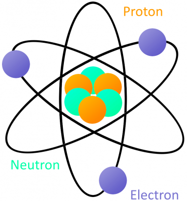
A very simple atom model. It’s not to scale but helpful for understanding how an atom is built. A core nucleus of protons and neutrons is surrounded by orbiting electrons.

Every atom must have at least one proton in it. The number of protons in an atom is important, because it defines what chemical element the atom represents. For example, an atom with just one proton is hydrogen, an atom with 29 protons is copper, and an atom with 94 protons is plutonium. This count of protons is called the atom’s atomic number.

The proton’s nucleus-partner, neutrons, serve an important purpose; they keep the protons in the nucleus and determine the isotope of an atom. They’re not critical to our understanding of electricity, so let’s not worry about them for this tutorial.

Electrons are critical to the workings of electricity (notice a common theme in their names?) In its most stable, balanced state, an atom will have the same number of electrons as protons. As in the Bohr atom model below, a nucleus with 29 protons (making it a copper atom) is surrounded by an equal number of electrons.

Copper Bohr model

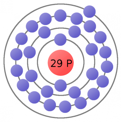
As our understanding of atoms has evolved, so too has our method for modeling them. The Bohr model is a very useful atom model as we explore electricity.

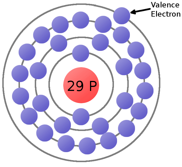
The atom’s electrons aren’t all forever bound to the atom. The electrons on the outer orbit of the atom are called valence electrons. With enough outside force, a valence electron can escape orbit of the atom and become free.Free electrons allow us to move charge, which is what electricity is all about. Speaking of charge…

Flowing Charges

As we mentioned at the beginning of this tutorial, electricity is defined as the flow of electric charge. Charge is a property of matter–just like mass, volume, or density. It is measurable. Just as you can quantify how much mass something has, you can measure how much charge it has. The key concept with charge is that it can come in two types:positive (+) or negative (-).

In order to move charge we need charge carriers, and that’s where our knowledge of atomic particles–specifically electrons and protons–comes in handy. Electrons always carry a negative charge, while protons are always positively charged. Neutrons (true to their name) are neutral, they have no charge. Both electrons and protons carry the sameamount of charge, just a different type.

Lithium atom with particle charges labeled

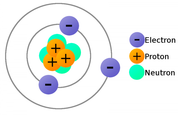
A lithium atom (3 protons) model with the charges labeled.

The charge of electrons and protons is important, because it provides us the means to exert a force on them. Electrostatic force!

Electrostatic Force

Electrostatic force (also called Coulomb’s law) is a force that operates between charges. It states that charges of the same type repel each other, while charges of opposite types are attracted together. Opposites attract, and likes repel.

Charges attract/repel

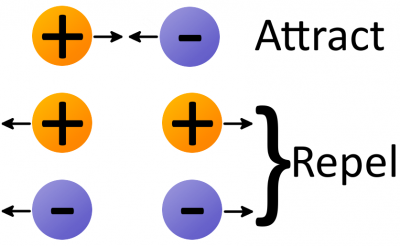
The amount of force acting on two charges depends on how far they are from each other. The closer two charges get, the greater the force (either pushing together, or pulling away) becomes.

Thanks to electrostatic force, electrons will push away other electrons and be attracted to protons. This force is part of the “glue” that holds atoms together, but it’s also the tool we need to make electrons (and charges) flow!

Making Charges Flow

We now have all the tools to make charges flow. Electrons in atoms can act as our charge carrier, because every electron carries a negative charge. If we can free an electron from an atom and force it to move, we can create electricity.

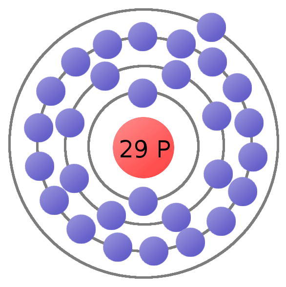
Consider the atomic model of a copper atom, one of the preferred elemental sources for charge flow. In its balanced state, copper has 29 protons in its nucleus and an equal number of electrons orbiting around it. Electrons orbit at varying distances from the nucleus of the atom. Electrons closer to the nucleus feel a much stronger attraction to the center than those in distant orbits. The outermost electrons of an atom are called the valence electrons, these require the least amount of force to be freed from an atom.

Copper atom with valence electron labeled

This is a copper atom diagram: 29 protons in the nucleus, surrounded by bands of circling electrons. Electrons closer to the nucleus are hard to remove while the valence (outer ring) electron requires relatively little energy to be ejected from the atom.

Using enough electrostatic force on the valence electron–either pushing it with another negative charge or attracting it with a positive charge–we can eject the electron from orbit around the atom creating a free electron.

Now consider a copper wire: matter filled with countless copper atoms. As our free electronis floating in a space between atoms, it’s pulled and prodded by surrounding charges in that space. In this chaos the free electron eventually finds a new atom to latch on to; in doing so, the negative charge of that electron ejects another valence electron from the atom. Now a new electron is drifting through free space looking to do the same thing. This chain effect can continue on and on to create a flow of electrons called electric current.

Simple electron flow

A very simplified model of charges flowing through atoms to make current.

Conductivity

Some elemental types of atoms are better than others at releasing their electrons. To get the best possible electron flow we want to use atoms which don’t hold very tightly to their valence electrons. An element’s conductivity measures how tightly bound an electron is to an atom.

Elements with high conductivity, which have very mobile electrons, are called conductors. These are the types of materials we want to use to make wires and other components which aid in electron flow. Metals like copper, silver, and gold are usually our top choices for good conductors.

Elements with low conductivity are calledinsulators. Insulators serve a very important purpose: they prevent the flow of electrons. Popular insulators include glass, rubber, plastic, and air.

Static or Current Electricity

Before we get much further, let’s discuss the two forms electricity can take: static or current. In working with electronics, current electricity will be much more common, but static electricity is important to understand as well.

Static Electricity

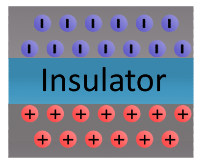
Static electricity exists when there is a build-up of opposite charges on objects separated by an insulator. Static (as in “at rest”) electricity exists until the two groups of opposite charges can find a path between each other to balance the system out.

Static electricity example

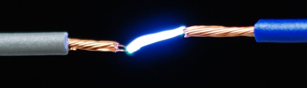
When the charges do find a means of equalizing, a static discharge occurs. The attraction of the charges becomes so great that they can flow through even the best of insulators (air, glass, plastic, rubber, etc.). Static discharges can be harmful depending on what medium the charges travel through and to what surfaces the charges are transferring. Charges equalizing through an air gap can result in a visible shock as the traveling electrons collide with electrons in the air, which become excited and release energy in the form of light.

Spark gap igniter static shock

Spark gap igniters are used to create a controlled static discharge. Opposite charges build up on each of the conductors until their attraction is so great charges can flow through the air.

One of the most dramatic examples of static discharge is lightning. When a cloud system gathers enough charge relative to either another group of clouds or the earth’s ground, the charges will try to equalize. As the cloud discharges, massive quantities of positive (or sometimes negative) charges run through the air from ground to cloud causing the visible effect we’re all familiar with.

Static electricity also familiarly exists when we rub balloons on our head to make our hair stand up, or when we shuffle on the floor with fuzzy slippers and shock the family cat (accidentally, of course). In each case, friction from rubbing different types of materials transfers electrons. The object losing electrons becomes positively charged, while the object gaining electrons becomes negatively charged. The two objects become attracted to each other until they can find a way to equalize.

Working with electronics, we generally don’t have to deal with static electricity. When we do, we’re usually trying to protect our sensitive electronic components from being subjected to a static discharge. Preventative measures against static electricity include wearing ESD (electrostatic discharge) wrist straps, or adding special components in circuits to protect against very high spikes of charge.

Current Electricity

Current electricity is the form of electricity which makes all of our electronic gizmos possible. This form of electricity exists when charges are able to constantly flow. As opposed to static electricity where charges gather and remain at rest, current electricity is dynamic, charges are always on the move. We’ll be focusing on this form of electricity throughout the rest of the tutorial.

Circuits

In order to flow, current electricity requires acircuit: a closed, never-ending loop of conductive material. A circuit could be as simple as a conductive wire connected end-to-end, but useful circuits usually contain a mix of wire and other components which control the flow of electricity. The only rule when it comes to making circuits is they can’t have any insulating gaps in them.

If you have a wire full of copper atoms and want to induce a flow of electrons through it,all free electrons need somewhere to flow in the same general direction. Copper is a great conductor, perfect for making charges flow. If a circuit of copper wire is broken, the charges can’t flow through the air, which will also prevent any of the charges toward the middle from going anywhere.

On the other hand, if the wire were connected end-to-end, the electrons all have a neighboring atom and can all flow in the same general direction.


We now understand how electrons can flow, but how do we get them flowing in the first place? Then, once the electrons are flowing, how do they produce the energy required to illuminate light bulbs or spin motors? For that, we need to understand electric fields.

Electric Fields

We have a handle on how electrons flow through matter to create electricity. That’s all there is to electricity. Well, almost all. Now we need a source to induce the flow of electrons. Most often that source of electron flow will come from an electric field.

What’s a Field?

field is a tool we use to model physical interactions which don’t involve any observable contact. Fields can’t be seen as they don’t have a physical appearance, but the effect they have is very real.

We’re all subconsciously familiar with one field in particular: Earth’s gravitational field, the effect of a massive body attracting other bodies. Earth’s gravitational field can be modeled with a set of vectors all pointing into the center of the planet; regardless of where you are on the surface, you’ll feel the force pushing you towards it.

Earth gravity field

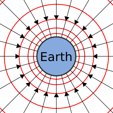
The strength or intensity of fields isn’t uniform at all points in the field. The further you are from the source of the field the less effect the field has. The magnitude of Earth’s gravitational field decreases as you get further away from the center of the planet.

As we go on to explore electric fields in particular remember how Earth’s gravitational field works, both fields share many similarities. Gravitational fields exert a force on objects of mass, and electric fields exert a force on objects of charge.

Electric Fields

Electric fields (e-fields) are an important tool in understanding how electricity begins and continues to flow. Electric fields describe the pulling or pushing force in a space between charges. Compared to Earth’s gravitational field, electric fields have one major difference: while Earth’s field generally only attracts other objects of mass (since everything is sosignificantly less massive), electric fields push charges away just as often as the attract them.

The direction of electric fields is always defined as the direction a positive test charge would move if it was dropped in the field. The test charge has to be infinitely small, to keep its charge from influencing the field.

We can begin by constructing electric fields for solitary positive and negative charges. If you dropped a positive test charge near a negative charge, the test charge would be attracted towards the negative charge. So, for a single, negative charge we draw our electric field arrows pointing inward at all directions. That same test charge dropped near anotherpositive charge would result in an outward repulsion, which means we draw arrows going out of the positive charge.

Electric fields of single charges

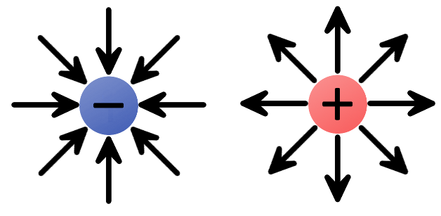
The electric fields of single charges. A negative charge has an inward electric field because it attracts positive charges. The positive charge has an outward electric field, pushing away like charges.

Groups of electric charges can be combined to make more complete electric fields.

Bigger e-field

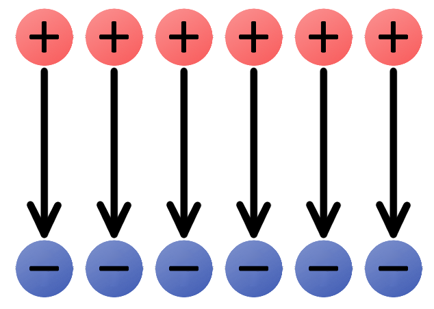
The uniform e-field above points away from the positive charges, towards the negatives. Imagine a tiny positive test charge dropped in the e-field; it should follow the direction of the arrows. As we’ve seen, electricity usually involves the flow of electrons–negative charges–which flow against electric fields.

Electric fields provide us with the pushing force we need to induce current flow. An electric field in a circuit is like an electron pump: a large source of negative charges that can propel electrons, which will flow through the circuit towards the positive lump of charges.

Electric Potential (Energy)

When we harness electricity to power our circuits, gizmos, and gadgets, we’re really transforming energy. Electronic circuits must be able to store energy and transfer it to other forms like heat, light, or motion. The stored energy of a circuit is called electric potential energy.

Energy? Potential Energy?

To understand potential energy we need to understand energy in general. Energy is defined as the ability of an object to do workon another object, which means moving that object some distance. Energy comes in many forms, some we can see (like mechanical) and others we can’t (like chemical or electrical). Regardless of what form it’s in, energy exists in one of two states: kinetic or potential.

An object has kinetic energy when it’s in motion. The amount of kinetic energy an object has depends on its mass and speed.Potential energy, on the other hand, is astored energy when an object is at rest. It describes how much work the object could do if set into motion. It’s an energy we can generally control. When an object is set into motion, its potential energy transforms into kinetic energy.

Gravitational potential energy

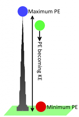
Let’s go back to using gravity as an example. A bowling ball sitting motionless at the top ofKhalifa tower has a lot of potential (stored) energy. Once dropped, the ball–pulled by the gravitational field–accelerates towards the ground. As the ball accelerates, potential energy is converted into kinetic energy (the energy from motion). Eventually all of the ball’s energy is converted from potential to kinetic, and then passed on to whatever it hits. When the ball is on the ground, it has a very low potential energy.

Electric Potential Energy

Just like mass in a gravitational field has gravitational potential energy, charges in an electric field have an electric potential energy. A charge’s electric potential energy describes how much stored energy it has, when set into motion by an electrostatic force, that energy can become kinetic, and the charge can do work.

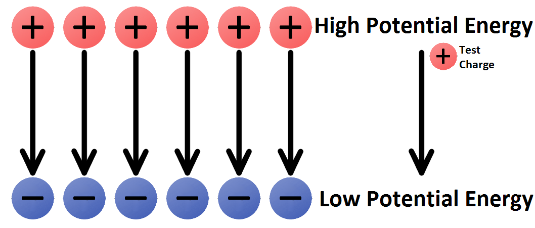
Like a bowling ball sitting at the top of a tower, a positive charge in close proximity to another positive charge has a high potential energy; left free to move, the charge would be repelled away from the like charge. A positive test charge placed near a negative charge would have low potential energy, analogous to the bowling ball on the ground.

Potential Energy in a field

To instill anything with potential energy, we have to do work by moving it over a distance. In the case of the bowling ball, the work comes from carrying it up 163 floors, against the field of gravity. Similarly, work must be done to push a positive charge against the arrows of an electric field (either towards another positive charge, or away from a negative charge). The further up the field the charge goes, the more work you have to do. Likewise, if you try to pull a negative chargeaway from a positive charge–against an electric field–you have to do work.

For any charge located in an electric field its electric potential energy depends on the type (positive or negative), amount of charge, and its position in the field. Electric potential energy is measured in units of joules (J).

Electric Potential

Electric potential builds upon electric potentialenergy to help define how much energy is stored in electric fields. It’s another concept which helps us model the behavior of electric fields. Electric potential is not the same thing as electric potential energy!

At any point in an electric field the electric potential is the amount of electric potential energy divided by the amount of charge at that point. It takes the charge quantity out of the equation and leaves us with an idea of how much potential energy specific areas of the electric field may provide. Electric potential comes in units of joules per coulomb (J/C), which we define as a volt (V).

In any electric field there are two points of electric potential that are of significant interest to us. There’s a point of high potential, where a positive charge would have the highest possible potential energy, and there’s a point of low potential, where a charge would have the lowest possible potential energy.

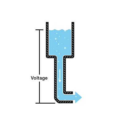
One of the most common terms we discuss in evaluating electricity is voltage. A voltage is the difference in potential between two points in an electric field. Voltage gives us an idea of just how much pushing force an electric field has.


With potential and potential energy under our belt we have all of the ingredients necessary to make current electricity. Let’s do it!

Electricity in Action!

After studying particle physics, field theory, and potential energy, we now know enough to make electricity flow. Let’s make a circuit!

First we will review the ingredients we need to make electricity:

  • The definition of electricity is the flow of charge. Usually our charges will be carried by free-flowing electrons.
  • Negatively-charged electrons are loosely held to atoms of conductive materials. With a little push we can free electrons from atoms and get them to flow in a generally uniform direction.
  • A closed circuit of conductive material provides a path for electrons to continuously flow.
  • The charges are propelled by anelectric field. We need a source of electric potential (voltage), which pushes electrons from a point of low potential energy to higher potential energy.

A Short Circuit

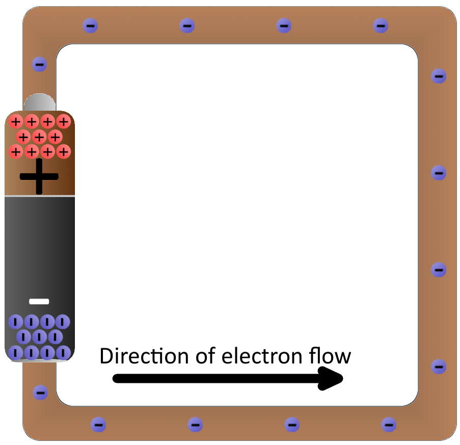
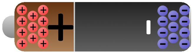
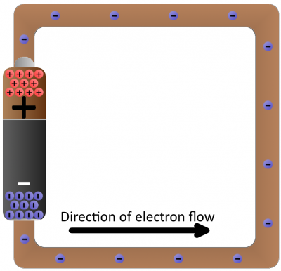
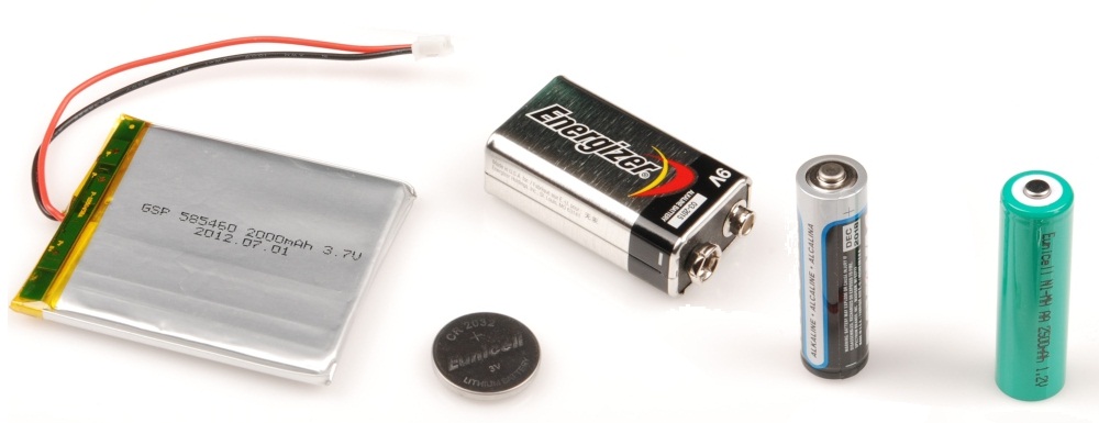
Batteries are common energy sources which convert chemical energy to electrical energy. They have two terminals, which connect to the rest of the circuit. On one terminal there are an excess of negative charges, while all of the positive charges coalesce on the other. This is an electric potential difference just waiting to act!

Battery with charges

If we connected our wire full of conductive copper atoms to the battery, that electric field will influence the negatively-charged free electrons in the copper atoms. Simultaneously pushed by the negative terminal and pulled by the positive terminal, the electrons in the copper will move from atom to atom creating the flow of charge we know as electricity.

Battery short circuit

After a second of the current flow, the electrons have actually moved very little–fractions of a centimeter. However, the energy produced by the current flow is huge, especially since there’s nothing in this circuit to slow down the flow or consume the energy. Connecting a pure conductor directly across an energy source is a bad idea. Energy moves very quickly through the system and is transformed into heat in the wire, which may quickly turn into melting wire or fire.

Illuminating a Light Bulb

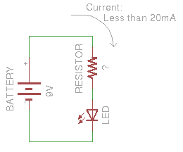
Instead of wasting all that energy, not to mention destroying the battery and wire, let’s build a circuit that does something useful! Generally an electric circuit will transfer electric energy into some other form–light, heat, motion, etc. If we connect a light bulb to the battery with wires in between, we have a simple, functional circuit.

Lightbulb animation

Schematic: A battery (left) connecting to a lightbulb (right), the circuit is completed when the switch (top) closes. With the circuit closed, electrons can flow, pushed from the negative terminal of the battery through the lightbulb, to the positive terminal.

While the electrons move at a snails pace, the electric field affects the entire circuit almost instantly (we’re talking speed of light fast). Electrons throughout the circuit, whether at the lowest potential, highest potential, or right next to the light bulb, are influenced by the electric field. When the switch closes and the electrons are subjected to the electric field, all electrons in the circuit start flowing at seemingly the same time. Those charges nearest the light bulb will take one step through the circuit and start transforming energy from electrical to light (or heat).

Analog vs Digital

Overview

We live in an analog world. There are an infinite amount of colors to paint an object (even if the difference is indiscernible to our eye), there are an infinite number of tones we can hear, and there are an infinite number of smells we can smell. The common theme among all of these analog signals is theirinfinite possibilities.

Digital signals and objects deal in the realm of the discrete or finite, meaning there is a limited set of values they can be. That could mean just two total possible values, 255, 4,294,967,296, or anything as long as it’s not ∞ (infinity).

Analog and digital real-life items

Real-world objects can display data, gather inputs by either analog or digital means. (From left to right): Clocks, multimeters, and joysticks can all take either form (analog above, digital below).

Working with electronics means dealing with both analog and digital signals, inputs and outputs. Our electronics projects have to interact with the real, analog world in some way, but most of our microprocessors, computers, and logic units are purely digital components. These two types of signals are like different electronic languages; some electronics components are bi-lingual, others can only understand and speak one of the two.

In this tutorial, we’ll cover the basics of both digital and analog signals, including examples of each. We’ll also talk about analog and digital circuits, and components.

Suggested Reading

The concepts of analog and digital stand on their own, and don’t require a lot of previous electronics knowledge. That said, if you haven’t already, you should peek through some of these tutorials:

Analog Signals

Define: Signals

Before going too much further, we should talk a bit about what a signal actually is, electronic signals specifically (as opposed to traffic signals, albums by the ultimate power-trio, or a general means for communication). The signals we’re talking about are time-varying“quantities” which convey some sort of information. In electrical engineering thequantity that’s time-varying is usually voltage(if not that, then usually current). So when we talk about signals, just think of them as a voltage that’s changing over time.

Signals are passed between devices in order to send and receive information, which might be video, audio, or some sort of encoded data. Usually the signals are transmitted through wires, but they could also pass through the air via radio frequency (RF) waves. Audio signals, for example might be transferred between your computer’s audio card and speakers, while data signals might be passed through the air between a tablet and a WiFi router.

Analog Signal Graphs

Because a signal varies over time, it’s helpful to plot it on a graph where time is plotted on the horizontal, x-axis, and voltage on the vertical, y-axis. Looking at a graph of a signal is usually the easiest way to identify if it’s analog or digital; a time-versus-voltage graph of an analog signal should be smooth andcontinuous.

Analog Sine Wave

While these signals may be limited to a rangeof maximum and minimum values, there are still an infinite number of possible values within that range. For example, the analog voltage coming out of your wall socket might be clamped between -120V and +120V, but, as you increase the resolution more and more, you discover an infinite number of values that the signal can actually be (like 64.4V, 64.42V, 64.424V, and infinite, increasingly precise values).

Example Analog Signals

Video and audio transmissions are often transferred or recorded using analog signals. The composite video coming out of an old RCA jack, for example, is a coded analog signal usually ranging between 0 and 1.073V. Tiny changes in the signal have a huge effect on the color or location of the video.

Composite video signal

An analog signal representing one line of composite video data.

Pure audio signals are also analog. The signal that comes out of a microphone is full of analog frequencies and harmonics, which combine to make beautiful music.

Digital Signals

Digital signals must have a finite set of possible values. The number of values in the set can be anywhere between two and a-very-large-number-that’s-not-infinity. Most commonly digital signals will be one of two values – like either 0V or 5V. Timing graphs of these signals look like square waves.

Square wave signal. Two values, either 0V or 5V.

Or a digital signal might be a discrete representation of an analog waveform. Viewed from afar, the wave function below may seem smooth and analog, but when you look closely there are tiny discrete steps as the signal tries to approximate values:

Digital Sine Wave

That’s the big difference between analog and digital waves. Analog waves are smooth and continuous, digital waves are stepping, square, and discrete.

Example Digital Signals

Not all audio and video signals are analog. Standardized signals like HDMI for video (and audio) and MIDII2S, or AC’97 for audio are all digitally transmitted.

Most communication between integrated circuits is digital. Interfaces like serialI2C, and SPI all transmit data via a coded sequence of square waves.

SPI square wave signals

Serial peripheral interface (SPI) uses many digital signals to transmit data between devices.

Analog and Digital Circuits

Analog Electronics

Most of the fundamental electronic components – resistorscapacitors, inductors, diodes, transistors, and operational amplifiers – are all inherently analog. Circuits built with a combination of solely these components are usually analog.

Example analog circuit

Analog circuits are usually complex combinations of op amps, resistors, caps, and other foundational electronic components. This is an example of a class B analog audio amplifier.

Analog circuits can be very elegant designs with many components, or they can be very simple, like two resistors combining to make avoltage divider. In general, though, analog circuits are much more difficult to designthan those which accomplish the same task digitally. It takes a special kind of analog circuit wizard to design an analog radio receiver, or an analog battery charger; digital components exist to make those designsmuch simpler.

Analog circuits are usually much moresusceptible to noise (small, undesired variations in voltage). Small changes in the voltage level of an analog signal may produce significant errors when being processed.

Digital Electronics

Digital circuits operate using digital, discrete signals. These circuits are usually made of a combination of transistors and logic gatesand, at higher levels, microcontrollers or other computing chips. Most processors, whether they’re big beefy processors in your computer, or tiny little microcontrollers, operate in the digital realm.

Example digital circuit

Digital circuits make use of components like logic gates, or more complicated digital ICs (usually represented by rectangles with labeled pins extending from them).

Digital circuits usually use a binary scheme for digital signaling. These systems assign two different voltages as two different logic levels – a high voltage (usually 5V, 3.3V, or 1.8V) represents one value and a low voltage (usually 0V) represents the other.

Although digital circuits are generally easier to design, they do tend to be a bit more expensive than an equally tasked analog circuit.

Analog and Digital Combined

It’s not rare to see a mixture of analog and digital components in a circuit. Although microcontrollers are usually digital beasts, they often have internal circuitry which enables them to interface with analog circuitry (analog-to-digital converterspulse-width modulation, and digital-to-analog converters. An analog-to-digital converter (ADC) allows a microcontroller to connect to an analog sensor (like photocells or temperature sensors), to read in an analog voltage. The less common digital-to-analog converter allows a microcontroller to produce analog voltages, which is handy when it needs to make sound.

Resources and Going Further

Now that you know the difference between analog and digital signals, we’d suggest checking out the Analog to Digital Conversiontutorial. Working with microcontrollers, or really any logic-based electronics, means working in the digital realm most of the time. If you want to sense light, temperature, or interface a microcontroller with a variety of other analog sensors, you’ll need to know how to convert the analog voltage they produce into a digital value.

Also, consider reading our Pulse Width Modulation (PWM) tutorial. PWM is a trick microcontrollers can use to make a digital signal appear to be analog

Voltage, Current, Resistance, and Ohm’s Law

Electricity Basics

When beginning to explore the world of electricity and electronics, it is vital to start by understanding the basics of voltage, current, and resistance. These are the three basic building blocks required to manipulate and utilize electricity. At first, these concepts can be difficult to understand because we cannot “see” them. One cannot see with the naked eye the energy flowing through a wire or the voltage of a battery sitting on a table. Even the lightning in the sky, while visible, is not truly the energy exchange happening from the clouds to the earth, but a reaction in the air to the energy passing through it. In order to detect this energy transfer, we must use measurement tools such as multimeters, spectrum analyzers, and oscilloscopes to visualize what is happening with the charge in a system. Fear not, however, this tutorial will give you the basic understanding of voltage, current, and resistance and how the three relate to each other.

alt text

Georg Ohm

Covered in this Tutorial

  • How electrical charge relates to voltage, current, and resistance.
  • What voltage, current, and resistance are.
  • What Ohm’s Law is and how to use it to understand electricity.
  • A simple experiment to demonstrate these concepts.

Electrical Charge

Electricity is the movement of electrons. Electrons create charge, which we can harness to do work. Your lightbulb, your stereo, your phone, etc., are all harnessing the movement of the electrons in order to do work. They all operate using the same basic power source: the movement of electrons.

The three basic principles for this tutorial can be explained using electrons, or more specifically, the charge they create:

  • Voltage is the difference in charge between two points.
  • Current is the rate at which charge is flowing.
  • Resistance is a material’s tendency to resist the flow of charge (current).

So, when we talk about these values, we’re really describing the movement of charge, and thus, the behavior of electrons. A circuit is a closed loop that allows charge to move from one place to another. Components in the circuit allow us to control this charge and use it to do work.

Georg Ohm was a Bavarian scientist who studied electricity. Ohm starts by describing a unit of resistance that is defined by current and voltage. So, let’s start with voltage and go from there.

Voltage

We define voltage as the amount of potential energy between two points on a circuit. One point has more charge than another. This difference in charge between the two points is called voltage. It is measured in volts, which, technically, is the potential energy difference between two points that will impart one joule of energy per coulomb of charge that passes through it (don’t panic if this makes no sense, all will be explained). The unit “volt” is named after the Italian physicist Alessandro Voltawho invented what is considered the first chemical battery. Voltage is represented in equations and schematics by the letter “V”.

When describing voltage, current, and resistance, a common analogy is a water tank. In this analogy, charge is represented by the water amount, voltage is represented by the water pressure, and current is represented by the water flow. So for this analogy, remember:

  • Water = Charge
  • Pressure = Voltage
  • Flow = Current

Consider a water tank at a certain height above the ground. At the bottom of this tank there is a hose.

Voltage is like the pressure created by the water.

The pressure at the end of the hose can represent voltage. The water in the tank represents charge. The more water in the tank, the higher the charge, the more pressure is measured at the end of the hose.

We can think of this tank as a battery, a place where we store a certain amount of energy and then release it. If we drain our tank a certain amount, the pressure created at the end of the hose goes down. We can think of this as decreasing voltage, like when a flashlight gets dimmer as the batteries run down. There is also a decrease in the amount of water that will flow through the hose. Less pressure means less water is flowing, which brings us to current.

Current

We can think of the amount of water flowing through the hose from the tank as current. The higher the pressure, the higher the flow, and vice-versa. With water, we would measure the volume of the water flowing through the hose over a certain period of time. With electricity, we measure the amount of charge flowing through the circuit over a period of time. Current is measured in Amperes (usually just referred to as “Amps”). An ampere is defined as 6.241*1018 electrons (1 Coulomb) per second passing through a point in a circuit. Amps are represented in equations by the letter “I”.

Let’s say now that we have two tanks, each with a hose coming from the bottom. Each tank has the exact same amount of water, but the hose on one tank is narrower than the hose on the other.

These two tanks create different pressures.

We measure the same amount of pressure at the end of either hose, but when the water begins to flow, the flow rate of the water in the tank with the narrower hose will be less than the flow rate of the water in the tank with the wider hose. In electrical terms, the current through the narrower hose is less than the current through the wider hose. If we want the flow to be the same through both hoses, we have to increase the amount of water (charge) in the tank with the narrower hose.

These two tanks create the same pressure.

This increases the pressure (voltage) at the end of the narrower hose, pushing more water through the tank. This is analogous to an increase in voltage that causes an increase in current.

Now we’re starting to see the relationship between voltage and current. But there is a third factor to be considered here: the width of the hose. In this analogy, the width of the hose is the resistance. This means we need to add another term to our model:

  • Water = Charge (measured in Coulombs)
  • Pressure = Voltage (measured in Volts)
  • Flow = Current (measured in Amperes, or “Amps” for short)
  • Hose Width = Resistance

Resistance

Consider again our two water tanks, one with a narrow pipe and one with a wide pipe.

The tank with the narrow pipe creates a higher resistance.

It stands to reason that we can’t fit as much volume through a narrow pipe than a wider one at the same pressure. This is resistance. The narrow pipe “resists” the flow of water through it even though the water is at the same pressure as the tank with the wider pipe.

The narrow pipe resists the flow.

In electrical terms, this is represented by two circuits with equal voltages and different resistances. The circuit with the higher resistance will allow less charge to flow, meaning the circuit with higher resistance has less current flowing through it.

This brings us back to Georg Ohm. Ohm defines the unit of resistance of “1 Ohm” as the resistance between two points in a conductor where the application of 1 volt will push 1 ampere, or 6.241×10¹⁸ electrons. This value is usually represented in schematics with the greek letter “Ω”, which is called omega, and pronounced “ohm”.

Ohm’s Law

Combining the elements of voltage, current, and resistance, Ohm developed the formula:

alt text

Where

  • V = Voltage in volts
  • I = Current in amps
  • R = Resistance in ohms

This is called Ohm’s law. Let’s say, for example, that we have a circuit with the potential of 1 volt, a current of 1 amp, and resistance of 1 ohm. Using Ohm’s Law we can say:

alt text

Let’s say this represents our tank with a wide hose. The amount of water in the tank is defined as 1 volt and the “narrowness” (resistance to flow) of the hose is defined as 1 ohm. Using Ohms Law, this gives us a flow (current) of 1 amp.

Using this analogy, let’s now look at the tank with the narrow hose. Because the hose is narrower, its resistance to flow is higher. Let’s define this resistance as 2 ohms. The amount of water in the tank is the same as the other tank, so, using Ohm’s Law, our equation for the tank with the narrow hose is

alt text

But what is the current? Because the resistance is greater, and the voltage is the same, this gives us a current value of 0.5 amps:

alt text

Tanks with their equivalent electrical meanings.

So, the current is lower in the tank with higher resistance. Now we can see that if we know two of the values for Ohm’s law, we can solve for the third. Let’s demonstrate this with an experiment.

An Ohm’s Law Experiment

For this experiment, we want to use a 9 volt battery to power an LED. LEDs are fragile and can only have a certain amount of current flowing through them before they burn out. In the documentation for an LED, there will always be a “current rating”. This is the maximum amount of current that can flow through the particular LED before it burns out.

Materials Required

In order to perform the experiments listed at the end of the tutorial, you will need:

NOTE: LEDs are what’s known as a “non-ohmic” devices. This means that the equation for the current flowing through the LED itself is not as simple as V=IR. The LED introduces something called a “voltage drop” into the circuit, thus changing the amount of current running through it. However, in this experiment we are simply trying to protect the LED from over-current, so we will neglect the current characteristics of the LED and choose the resistor value using Ohm’s Law in order to be sure that the current through the LED is safely under 20mA.

For this example, we have a 9 volt battery and a red LED with a current rating of 20 milliamps, or 0.020 amps. To be safe, we’d rather not drive the LED at its maximum current but rather its suggested current, which is listed on its datasheet as 18mA, or 0.018 amps. If we simply connect the LED directly to the battery, the values for Ohm’s law look like this:

alt text

therefore:

alt text

and since we have no resistance yet:

alt text

Dividing by zero gives us infinite current! Well, not infinite in practice, but as much current as the battery can deliver. Since we do NOT want that much current flowing through our LED, we’re going to need a resistor. Our circuit should look like this:

alt text

We can use Ohm’s Law in the exact same way to determine the reistor value that will give us the desired current value:

alt text

therefore:

alt text

plugging in our values:

alt text

solving for resistance:

alt text

So, we need a resistor value of around 500 ohms to keep the current through the LED under the maximum current rating.

560 ohm resistor.

500 ohms is not a common value for off-the-shelf resistors, so this device uses a 560 ohm resistor in its place. Here’s what our device looks like all put together.

Success!

Success! We’ve chosen a resistor value that is high enough to keep the current through the LED below its maximum rating, but low enough that the current is sufficient to keep the LED nice and bright.

This LED/current-limiting resistor example is a common occurrence in hobby electronics. You’ll often need to use Ohm’s Law to change the amount of current flowing through the circuit. Another example of this implementation is seen in the LilyPad LED boards.

LilyPad Battery Board with a LilyPad LED Board

With this setup, instead of having to choose the resistor for the LED, the resistor is already on-board with the LED so the current-limiting is accomplished without having to add a resistor by hand.

Current Limiting Before or After the LED?

To make things a little more complicated, you can place the current limiting resistor on either side of the LED, and it will work just the same!

Many folks learning electronics for the first time struggle with the idea that a current limiting resistor can live on either side of the LED and the circuit will still function as usual.

Imagine a river in a continuous loop, an infinite, circular, flowing river. If we were to place a dam in it, the entire river would stop flowing, not just one side. Now imagine we place a water wheel in the river which slows the flow of the river. It wouldn’t matter where in the circle the water wheel is placed, it will still slow the flow on the entire river.

This is an oversimplification, as the current limiting resistor cannot be placed anywhere in the circuit; it can be placed on either side of the LED to perform its function.

For a more scientific answer, we turn toKirchoff’s Voltage Law. It is because of this law that the current limiting resistor can go on either side of the LED and still have the same effect. For more info and some practice problems using KVL, visit this website.

Resources and Going Further

Now you should understand the concepts of voltage, current, resistance, and how the three are related. Congratulations! The majority of equations and laws for analyzing circuits can be derived directly from Ohm’s Law. By knowing this simple law, you understand the concept that is the basis for the analysis of any electrical circuit!

These concepts are just the tip of the iceberg. If you’re looking to study further into more complex applications of Ohm’s Law and the design of electrical circuits, be sure to check out the following tutorials.

Industrial Electrical Symbols

Pumping Solutions Inc. offers this guide to common industrial electrical symbols to help you correctly identify components and spot potential hazards. Bookmark this page as a handy reference for future electrical projects. Safety first!


Partial Glossary

Resistor: Resistors restrict the flow of current. Used with a capacitor in a timing circuit.

Ground: Connection to the actual ground or other “grounding” structure. Used to provide electrical shock protection and for zero potential reference.

Capacitor: Stores electric charge. Can be used to filter or block DC signals while passing AC signals. Used with a resistor in a timing circuit.

Battery: Generates constant voltage and supplies electrical energy.

Fuse: Sacrificial overcurrent protection device. This symbol represents low power/low voltage fuses.

Inductor: Coil of wire that generates a magnetic field when electrical current is passed through it. Passive two-terminal electrical component used to store energy in the resulting magnetic field. Can also be used as a transducer to convert electrical energy into mechanical energy.

Iron Core Inductor: Same as above, but with an iron core beneath the coiled wire.

Circuit Breaker: Automatically operated electrical switch that protects electrical circuits from damage caused by short circuits or overloads.

Voltmeter: Very high resistance device used to measure electrical voltage. Must be connected in parallel.

Ammeter: Zero resistance device used to measure electrical current. Must be connected serially.

Wattmeter: Device used to measure electric power.

Bell: Electric bell, makes a single tone or repeated ringing sound when activated.

Buzzer: Similar to an electric bell, an electric buzzer makes a constant buzz when activated.


SPST (Single-Pole, Single-Throw): A simple switch with one input and one output. Switch will be either closed or completely disconnected. Requires only two terminals. Ideal for on/off switching.

SPDT (Single-Pole, Double-Throw): A switch utilizing three terminals: one common pin, two pins vying for connection to the common (only one can be connected at a time). Ideal for selecting between two power sources or swapping inputs. Can be made into an SPST switch by simply leaving one of the throw pins unconnected.

DPST (Double-Pole, Single-Throw): Essentially a doubled SPST. A switch with two inputs and two outputs; each input corresponds to one of the outputs. DPST switches provide versatility, as they can accept two inputs and drive two different outputs to the same circuit.

DPDT (Double-Pole, Double-Throw): Essentially two SPDT switches, controlling two different circuits, and always switched on together from a single actuator. Require six terminals.

NO (Normally Open): The “normal” state for a switch is its nonactuated position. Depending on its construction, a switch’s normal state can produce an open circuit or a short circuit. When open until actuated, a switch is a normally open (NO) switch; when activated, a NO switch closes the circuit.

NC (Normally Closed): Essentially the “opposite” of an NO switch. A switch that creates a short circuit when not actuated. Normally closed (NC) switches create a short circuit when actuated.

Magnetic Circuit with Air Gap

Magnetic Circuit 

When a magnetic flux is circulated or follow through a closed area or path, is called the magnetic circuit or when a magnetic field circulates in a closed path represented as lines of magnetic flux in a confined area is called Magnetic Circuit. This magnetic circuit forms with permanent magnets or electromagnets and confined to the path by magnetic cores consisting of ferromagnetic materials like iron etc.

MMF


A circulating force called
Magneto Motive Force (MMF) or magnetic potential is responsible for establishing magnetic flux in a magnetic circuit. The MMF is equivalent to a number of wire carrying an electric current and has units of ampere turns. MMF is the property of certain substances or phenomena that gives rise to a magnetic field and is analogous to electromotive force or voltage of electricity.

If the flux is so divided that is enclosed to a portion of the device and part to another, the magnetic circuit is called parallel magnetic circuit and if all the flux is confined to a single closed loop, as in a ring-shaped electromagnet, the circuit is called a series magnetic circuit.

Air Gap in Magnetic Circuit


Now if questioned what
air gap in magnetic circuit is? , then the answer would be a prevention to the saturation in general. Air is a kind of insulator to electricity as well as magnetism, i.e. area with negativity is used for positive results. Like air, it can be as paint, gas, vacuum, aluminium etc. to prevent core saturation depending upon application of use. But sometimes in transformer the air gap fails to prevent saturation caused by excessive AC voltage polarization.magnetic circuit with air gap
Air is a non-magnetic part of a magnetic circuit that connects serially and magnetically all the other parts in the circuit to make the flux to flow through the gap. Air gap has a significant character to enhance electrified parts to move physically in magnetic fields, without touching each other.
The air gap in magnetic circuit means the magnetic
resistance, i.e. reluctance to the magnetic flux density. The reluctance of a magnetic circuit is proportional to its length & inversely proportional to its cross-sectional area and a magnetic property of the given material called its permeability. To calculate reluctance:
Magnetic Reluctance (R) = L/Aμμ
o
L = Length of circuit
A = Cross-sectional area of the circuit
μ = Permeability
μ
o = Relative magnetic permeability
The air gap is mostly used in applications where the magnetic saturation concludes as a high risk as magnetic saturation causes loss of inductance, increasing of current, power loss in the circuit. But implementation of air gap in a
magnetic circuit influences the parameters of magnetic inductor also i.e. addition of reluctance (air) in the circuit changes the B-H curve (allows driving the inductor at higher current, therefore higher magnetic fieldstrength, thus extending the range before magnetic saturation occurs), decrease the inductance and increasing the saturation current of magnetic inductor. The problem which an air gap solves in a core is the excessive flux produced with a high level of current in the windings.

Another phenomenon of flux in magnetic circuit is that most of the flux is confined to the intended path use of magnetic cores (ferromagnetic material), but a small amount of flux always complete its path through the surrounding air called the leakage flux. So whenever an air gap is put-up in magnetic core, flux fringes out into the neighboring air path and such paths for flux called flux fringing resulting in non-uniform flux density in the air gap and dropping of MMF. The largest is the air gap, the more is the flux fringing and vice versa. A magnetic circuit resembles as a “conductor” so that the magnetic field can put along the desired path. If a high permeability material is used, then very little energy will be stored in the magnetic core. However, the air gap has an advantage of discontinuity and due to its low permeability stores significant amount of magnetic energy, as compared to the same volume of magnetic core before the saturation

Source of Electrical Energy

There are two types of sources of electrical energy

  1. Ideal Voltage Source
  2. Ideal Current Source


Ideal Voltage Source


An ideal voltage source is a two terminal element which maintains a terminal
voltage regardless of the value of the current through its terminals. An ideal voltage source can maintain the fixed voltage independent of the load resistance. The internal resistance of an ideal voltage source is equal to zero.
ideal voltage source
Although ideal sources do not exist in reality so in a practical
voltage source the voltage across the terminals of the source keeps falling as the current through it increases.

This behavior can be explained by putting a resistance in series with an ideal voltage source as shown in figure below.
practical voltage source
Then the terminal voltage V as
V = v(t) – i R
Examples of voltage sources – Batteries and Electrical Generators are normally used as voltage sources.

Ideal Current Source


An ideal current source is a two terminal element which maintains a current flowing through its terminals regardless of the value of the terminal voltage. The internal resistance of ideal current source is infinite.
ideal current source
In a practical current source the current through the source decreases as the voltage across it increases, this behavior can be explained by putting a resistance in parallel with the terminals of the current source as shown in the figure.
practical current source
Then the terminal current is given by

Examples of
current sources– Most of the semiconductor devices like transistor etc. are treated as current sources.

Dependent Energy Sources


The two types of sources that we have discussed up to now are called independent sources because the value of the source quantity is not affected in any way by activities in the remainder of the circuit. In dependent sources the source quantity is determined by a voltage or current existing some other location.
dependent energy source

Electrical Source Transformation


A current source is dual form of a voltage source and a voltage source is dual form of a current source. A voltage source can be converted into equivqlent current source and a current source can also be converted into equivalent voltage source. We can understand the conversion process as

Voltage Source to Current Source Conversion


Assume a voltage source with terminal voltage V and the internal resistance r. Now according to the
Ohm’s law current through the source can be calculated as

This current is supplied by the equivalent current source and same resistance r will be connected across the source. Voltage source to current source conversion is shown in the following figure
voltage to current source transformation

Current Source to Voltage Source Conversion


Similarly assume a current source with value I and internal resistance r. Now according to the Ohm’s law the voltage across the source can be calculated as

current to voltage source transformation